


SKU 47821 For technical questions, please call 1-800-444-3353 Page 11
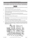
Mounting the Control Box
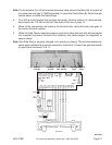
1. Find a secure location for the Control Box (B) within two feet of the Actuator Arm (A).
It has to be close because one of the Actuator Arm cables goes directly into the Control
Box (B). See the illustration on page 9.
2. Open the Control Box and find the four mounting screw holes. Being careful not to touch
the circuit board inside the box, hold the box against the surface where it will be mounted
and make a drill mark on the mounting surface.
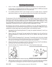
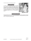
3. Drill out five cable holes at the bottom of the Control Box. The Cable Inlet Nuts and Bolts
(L) must be mounted in these holes before any cables are inserted. See photo at the
middle of page 12. Use conduit connectors (not supplied) if conduit is routed directly to
the Control Box.
4. Drill four holes in the mounting surface and secure the Control Box with hardware not
supplied.
Placement of Accessories
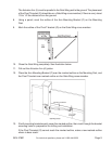
1. Mount the Warning Light (E) in a location where it can be easily seen from both sides
of the gate. When flashing, it indicates that the gate wings are opening or closing — stay
clear. Mount the Warning Light with hardware, not supplied. Connect two-pair cable (not
supplied) to the Warning Light (E) and route to the bottom of the Control Box (B). If cable
needs to be buried, conduit must be used. The Warning Light bulb uses 12 volts at 10
watts.
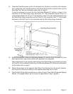
2. Mount the Key Switch (D) in a location where it can be reached from outside of the
gate wings (mounting hardware not supplied). Try to hide it from public view. When a key
is placed in it and turned, the gate wings will open. The two-pair cable (not supplied),
once connected within the Key Switch box, should be routed through a wall or conduit
to prevent tampering from outside. Route cable to the bottom of the Control Box (B).
3. Mount the Antenna (N) as high as possible, and within its cable length from the Control
Box (B). Mounting hardware not supplied. Route the cable to the bottom of the Control
Box (B).
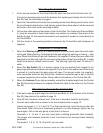
Wire Connections to the Control Box
1. Push each cable up and through the Inlet Nuts and Bolts (L) at the bottom of the Control
Box (B). See photo at the middle of page 12.
2. Strip 3/8 inch insulation off each wire. If the wire is stranded, twist the lead tightly.
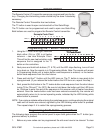
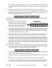
3. Connect each cable wire as shown in the circuit board photo on page 12.
Loosen lug screws 1, 2, 3, 5, and 12-17 on the terminal strip. Insert the wire in the hole
from above. When the wire is completely pushed in (no wire showing), tighten the lug
screw again. Pull on the wire gently to test that it is secure.
Terminals 4, 5, 10 and 11 are only used when installing photocells (Not Included).
The jumper wire between terminals 4 and 5 will need to be removed when installing
photocells.
Terminals 6, 7, 8, 9, 18, 19, 20 and 21 are not used.