


SKU 47821 For technical questions, please call 1-800-444-3353 Page 7
INSTALLATION INSTRUCTIONS
Warning: Installation of the Gate Opener requires knowledge of mechanical and electrical
concepts and experience. If you do not have these, you should contract a qualified technician
to do the installation. Electrical supply wiring must be done by a licensed electrician.
Preparation
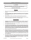
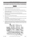
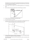
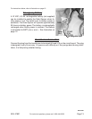
1. Verify that the gate wings swing open easily, and without obstructions such as scraping
the ground. See illustration below.
2. Verify that each gate wing does not weigh over 550 pounds.
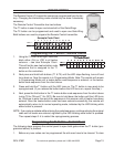
3. Determine a location for the Control Box within two feet of either Actuator Arm (A).
It may be mounted to the pillar or post supporting the gate. It should also be on the gate
side with electrical access.
4. Determine the 110 VAC, 20A, circuit source to power the Gate Opener.
The connection can be completed with conduit (or other approved means) going directly
to the Control Box (B).
5. Select a location to mount the Warning Light (E).
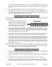
6. Determine the conduit route from the far Actuator Arm (A), across the drive way, to the
Control Box (B).
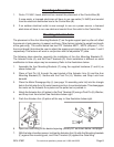
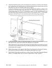
7. Purchase hardware to secure the Brackets (F and G) to the gate post and gate wings,
and to mount the Control Box (B). See illustrations on page 8.
In some cases, it may be necessary to weld the Pivot T-brackets (G) to the gate.
8. Purchase conduit and two-pair cable (18-20 gauge AWG solid) for the Warning Light (E),
Key Switch (D), and far Actuator Arm (A). The conduit for the far actuator arm will have
weight pass over it and must be designed to withstand the stresses created by heavy
loads passing overhead.