


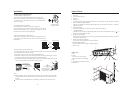
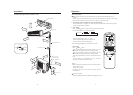
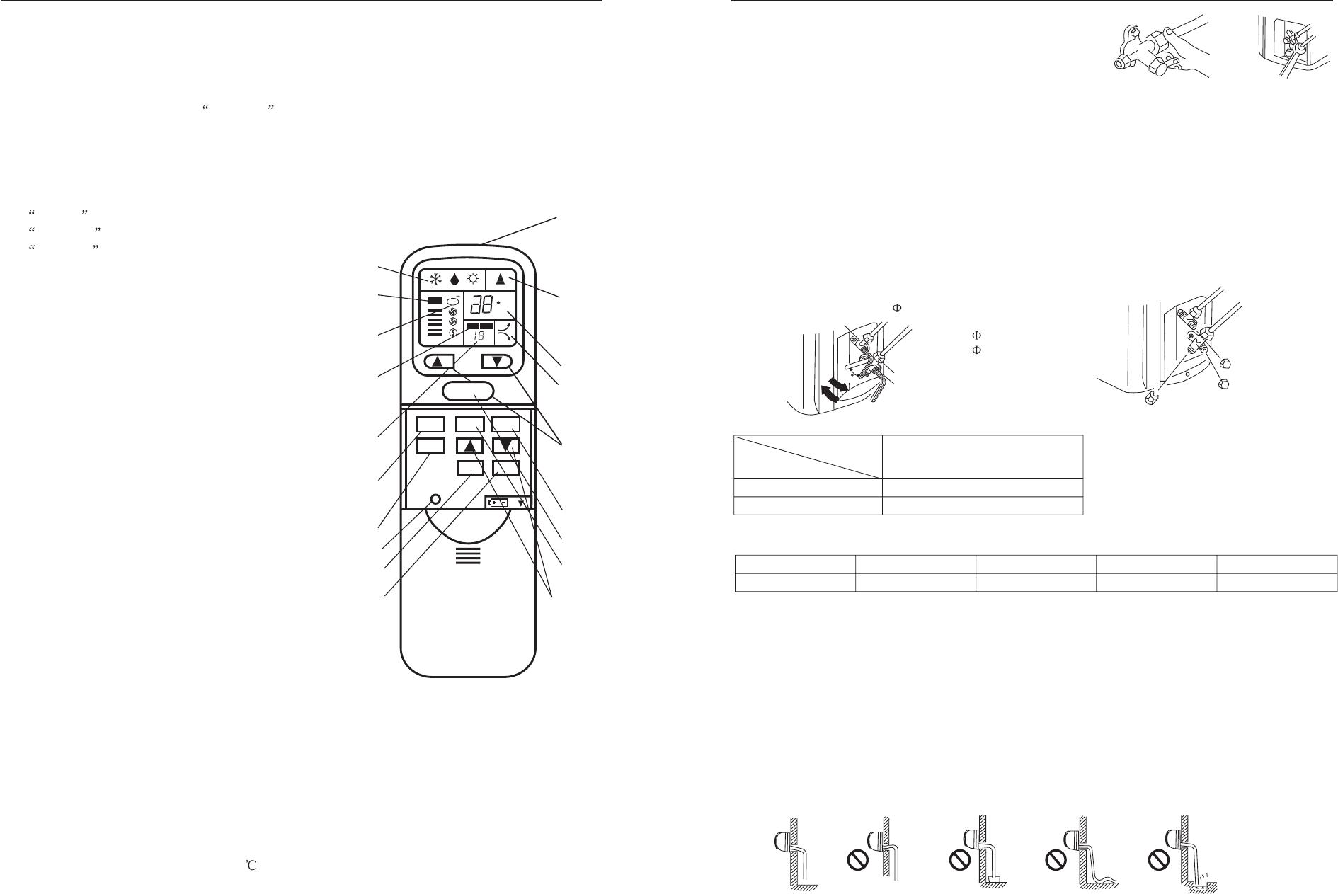
Name of Parts
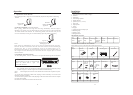
Introduction to Display and Function:
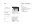
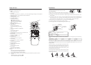
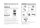
1. Mode
Mode selected is displayed
2. Air Volume
Indicating the air speed, when automatic is set, the air speed changes according to the temperature
difference between the indoor temperature and set temperature.
3. Healthy Operation
Indicating healthy operation
4. Timing Mode Display
Indicating time set mode:
Normal for non-time-set;
Timed off for timed turning off;
Timed on for timed turning on;
5. Indicating the Time set
Indicating the time set on and off
6. Mode Selection
Selecting the modes below:
cooling, dehumidifying, and heating
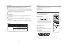
7. Timer
Used to select TIMER ON, TIMER OFF
8. Time Set
To set the time on and off
9. Signal Sending Head
To send signal into the signal receiver on the indoor unit
10. Signal Display
It blinks when the signal is being sent
11. Temperature Display
To display the temperature set
12. Temperature Set
To set the desired room temperature
13. On/Off Button
To turn on and turn off the air conditioner
14. Air Volume
To select the desired air speed
15. Air flow Direction
To adjust the air flow direction
16. Healthy Button
To set the healthy operation
17. Power Button
To set super or soft operation
18. Indication for Power Operation
19. Reset
When the remote controller appears abnormal,
use a sharp pointed item to press this button to
reset the remote controller to normal condition.
Notes: After replacing the batteries in the remote controller, press on/off button, the mode is resumed
as below:
Mode: Refrigerating; Temperature:26
Timer: Normal; Fan Speed: Automatic
4
Remote Controller:
AUTO
C
ON OFF
H
ion
1
9
10
11
18
12
13
14
15
8
2
3
4
5
6
7
17
19
16
FAN
HEALTH
POWER
TIMER
TEMP
ON/OFF
MODE
RESET
SWING
2
9
90
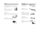
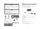
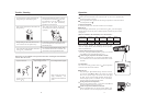
Two-way Valve
9.52mm(3/8")
12.7mm(1/2")
Liquid Side
6.35mm(1/4")
Gas Side
Mouth Nut
Three-way Valve
Open
Piping Connection for Outdoor Unit
Connect the Piping and Inlet and Outlet Liquid Tubes
Gas Drainage Method:
Drain the air in the indoor unit and the pipes as per the drawing:
(1) Remove the valve cap on the two-way valve of the indoor unit with a spanner.
(2) Unscrew by 1/2 cycle the nut on the mouth of the thick pipe connected with the three-way valve
with a spanner.
(3) Unscrew the spool of the two-way valve by 90 with an inner hexagon spanner, and after about 10
seconds,close the two-way valve,then air will be drained out from the mouth of the thick pipe. When
the air is drained out, screw tightly the nut on the mouth according to there quired torque.
(4) Open the two-way valve and three-way valve with an inner hexagon spanner.
(5) Check the leakage with soap liquid or a leakage checker.
(6) Screw tightly the two valve caps according to the required torque.
o
Notes: When the pipe is extended, the air in the connection pipe shall be drained out with the
refrigerant(R22) from outside the system, then the excess refrigerant shall be drained out as per the air
drainage method.
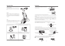
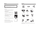
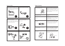
Check the Layout of the Drain Pipe and Connection Wires
The drain pipe should be placed underneath, and the connection
wires should be plac upside; and the drain pipe especially the
section inside the machine and indoors must be wound up with
insulating material to preserve heat
ed
The drain pipe shall be sloped and no concave and convex shall
occur along the whole pipe. And the cases as the right drawing
indicates shall not occur.
Specif.
Valve Spool
Valve Cap
Pipe Length
Refrigerant filled
5m
none
7m
32g
10m
80g
15m
160g
7-9
20-25
Torque Tight screw N. M
Required Torque
When the connection pipe is more than 5 cm, it shall be filled with refrigerant as per the following
form:
Correct Up-bent End in the Water Ripple Bad Smell in the Pool
Prohibited Prohibited Prohibited Prohibited
Installat
i
on