


30
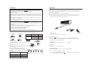
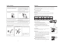
Wiring for Indoor and Outdoor Units
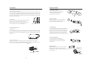
1. Wiring Method for Ring Terminal
The wiring method is as the drawing below for the ring terminal:
Remove the connection screw and put the screw through the ring on
the connection wire terminal, then connect it to the terminal blocks,
then screw it tightly.
2.Wiring Method for Line Terminal
The wiring method is as follows for the non-ring terminal:
Loosen the connection screw and insert the connection wire end into the
terminal block completely, screw it tightly, then slightly pull out the
connection wire to ensure it be clamped tightly.
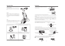
3. Method for Pressing the Connection Wire
After wiring, the connection wire must be pressed tightly with a wire-
pressing clip, which should press the outer sleeves of the wire as the
right drawing:
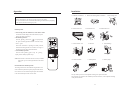
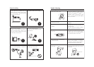
Wiring for Indoor Unit and Outdoor Unit
Lay out the connection wires as the connection drawing (Notes: The two ends of the connection
wires are different, never connect reversely)
1) Open the wire cover, unscrew the pressing clamp(outdoor unit).
2) Connect the connection wires as per the wiring method and the wiring drawing (the wires on
the indoor unit shall be inserted from behind as the attached drawing).
3) Ensure that the terminals are clamped tightly, and press the connection wires(outdoor unit) as
per the pressing method, then install the wire-pressing cover.
Notes:
When connecting the wires of indoor and outdoor units, check the numbers on the terminals
of the indoor and outdoor units,the same wire shall connect the same number and color
terminal
Wrong connection would damage the air conditioner
,
s controller,or the unit cannot work.
Air Inlet Grille
Pressing Cover
Screw
Terminals
Pressing Clamp
Power Supply Wire
Indoor and Outdoor
Connec ion Wirest
Correct Pressing Wrong Pressing
Terminal
block
Pressing
Clamps
Wiring Method for
Ring Terminal Block
Installat
i
on
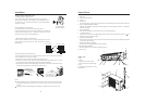
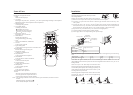
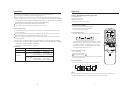
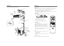
Name of Parts
Indoor Unit:
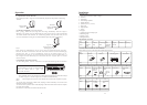
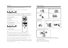
Outdoor Unit:
1. Inlet Grill
2. Anion Generator (inside)
3. Air Filter
4. Swing louver
It can be adjusted to upward or downward with the remote controller only (Do not adjust it manually)
5. Power or Healthy Operation Indicator
After the air conditioner is started, this indicator lights up; when the healthy operation is started,this
indicator turns green.
6. Timer Set Indicator
When the air conditioner is at the state of time-set, this indicator lights up.
7. Test
This button is only used for test refrigerating operation when the room temperature is below 16 , so it
should not be used in normal situation.
8. Emergency Manual Button
When the remote controller is lost or cannot be used, this button can make the air conditioner continue
to operate for the time being.
9. Remote Signal Receiving Window
It receives the remote signal from the remote controller.
10. Working Method Indicator
When the compressor is working, the indicator lights up .
11. Power Plug
Manual Button
1. Inlet
2. Outlet
Send out hot air when cooling,
and send out cold air when heating .
3. Inlet
4. Connection pipe and electric wiring.
5. Drain Hose
1
1
2
2
3
4
4
5
6
5
7
8
9
10
11
3
3