


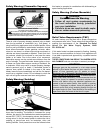
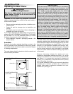
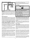
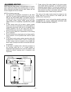
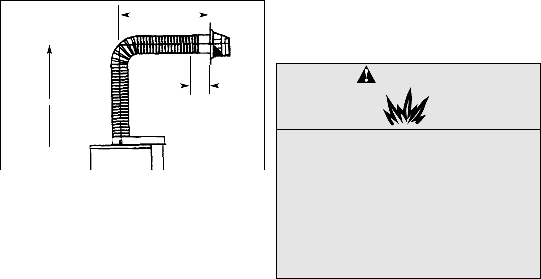
High rise vent pipe arrangement
Figure 3M
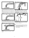
When the height H (From vent terminal center line to bottom
of heater) is over 2.28m (90 in.), it is a high rise vent pipe
arrangement. In this case, the minimum distance “D” from
the center of the water heater to the outside wall surface is
560mm (22 in.), and the maximum height of “H” is 3.66m
(12 ft.).
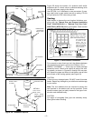
Gas Connections
Install the gas piping as indicated in Figure 2A. Use only
new pipe and fittings with sound, clean-cut pipe threads.
Sealing compound must conform to the applicable code for
pipe sealing compound approved for use with natural gas
and propane. Use gas piping of adequate sizing to ensure
full gas input. All piping must comply with all local codes. In
the absence of local codes, piping must comply with the
rules stated by the applicable "Natural Gas and Propane
Installation Code" CAN/CSA-B149.1 or "National Fuel
Gas Code" ANSI Z223.1 (NFPA 54). The final connection
to the gas control valve is made using 1/2”. NPT pipe.
Inlet gas pressure to the appliance must not exceed the gas
pressures marked on the rating plate; 7.0 in. w.c. (1.7 kPa)
for natural gas, 14 in. w.c. (3.5 kPa) for L.P. gas. The mini-
mum supply pressure for the purpose of input adjustment is
1 in. w.c. (0.25 kPa) above manifold pressure.
The appliance and its individual shut-off valve must be dis-
connected from the gas supply piping system during any
pressure testing of that system at test pressure in excess of
14 in. w.c. (3.5 kPa).
The appliance must be isolated from the gas supply piping
system by closing its individual manual shut-off valve during
any pressure testing of the gas supply piping system at test
pressures equal to, or less than 14 in. w.c. (3.5 kPa).
The appliance and its gas connection must be leak tested
before placing the appliance in operation. It is important to
have a readily accessible manual shut-off valve in the gas
line supplying the water heater. This shut-off valve must be
close to the heater. In addition, a drip leg must be installed
ahead of the gas control valve to help trap sediment and for-
eign material.
A ground-joint union must be installed ahead of the gas
valve to permit easy removal of the unit. All leak testing
must be done with a soapy water solution.
NEVER USE A MATCH OR OPEN FLAME TO TEST FOR
GAS LEAKS. A FIRE OR EXPLOSION COULD RESULT.
Gas Supply
Read the data plate to be sure the water heater is made
for the type of gas you will be using in your home. This
information will be found on the data plate located above the
gas control valve. If the information does not agree with the
type of gas available, do not install or attempt to start. Call
your dealer.
Note: An odourant is added by the gas supplier to the gas
used by this water heater. This odourant may fade over an
extended period of time. Do not depend upon this odourant
as an indication of leaking gas.
Water Piping
Pipes and fittings should be installed in compliance with the
installation drawing. Check for dip tube in cold water fitting
before connection of hot and cold water lines. It is recom-
mended that a shut-off valve be located in the cold-water
supply line in close proximity to the cold water inlet of the
water heater. Show the user where this water shut-off valve
is installed and how to use it to shut the water supply to the
heater off.
Connect the cold water supply (3/4” NPT) to the fitting
marked “COLD”, the hot water outlet (3/4” NPT) to the fitting
marked “HOT”. Do not apply heat to either of these fittings
as they contain a nonmetallic tube. Solder the pipe to an
adapter before attaching the adapter to the hot and cold
water fittings. When making these connections, always use
a good grade of pipe joint compound and be certain that all
fittings are tight. See installation drawing (Figure 2A).
After piping has been installed, allow tank to fill with water
and check connections for leaks. To ensure complete filling
of the tank, allow air to exit by opening the nearest hot water
faucet until a constant flow of water is obtained.
– 9 –
H
TO BOTTOM
OF HEATER
D
WALL THICKNESS
254mm
(10 in.)
(REF)
DANGER
Explosion Hazard
• Use a new CSA approved gas supply line.
• Install a gas supply shut-off valve.
• Do not connect a natural gas water heater
to a L.P. gas supply.
• Do not connect a L.P. gas water heater to
a natural gas supply
• Failure to follow these instructions can
result in death, an explosion or carbon
monoxide poisoning.