


III) INSTALLATION
Unpacking the Water Heater
Important: Do not remove any permanent instructions,
labels, or the data label from outside of the water heater or
on the inside of panels.
• Remove exterior packaging and place installation com-
ponents aside.
• Inspect all parts for damage prior to installation and
start-up.
• Completely read all instructions before attempting to
assemble and install this product.
If you observe damage to the water heater or any of its com-
ponents, DO NOT ASSEMBLE OR INSTALL IT OR MAKE
ANY ATTEMPT TO FIX THE DAMAGED PART(S). Contact
the place of purchase for further instructions.
• After installation, dispose of packaging material in the
proper manner.
Location
Generally, the location selected should be as close to the
wall as practical and as centralized with the piping system
as possible. Heater should be located in an area not subject
to freezing temperatures.
The water heater should be located so that the controls and
drain are easily accessible.
CAUTION: When this water heater is installed directly on
carpeting, carpeting must be protected by a metal or wood
panel beneath the appliance extending beyond the full width
and depth of the appliance by at least 76mm (3 in.) in any
direction, or if the appliance is installed in an alcove or clos-
et, the entire floor must be covered by the panel. The panel
must be strong enough to carry the weight of the heater
when full of water. Failure to heed this warning may result in
a fire hazard.
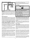
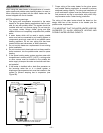
Minimum clearances between the heater and com-
bustible/non combustible materials are 0mm (0 in.) at the
sides and rear; 508mm (20 in.) from the top of water heater
and 25mm (1 in.) around the vent pipe. A minimum of
915mm (3 ft.) of clearance is required at the front (control)
side of the heater for service.
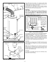
For a closet installation, the door at burner side should be
openable and a minimum of 102mm (4 in.) clearance is
needed. Water heater is certified for installation on a com-
bustible floor (see Figure 1).
– 5 –
0mm (0 in.)
0mm (0 in.)
ALCOVE INSTALLATION
(TOP VIEW)
0mm (0 in.)
0mm (0 in.)
CLOSET INSTALLATION
(TOP VIEW)
102mm (4 in.)
CLOSET DOOR
Figure 1 Minimum Installation Clearances
IMPORTANT:
This water heater must be installed strictly in accordance
with the instructions enclosed, and local electrical, fuel
and building codes. It is possible that connections to the
water heater, or the water heater itself, may develop
leaks. IT IS THEREFORE IMPERATIVE that the water
heater be installed so that any leakage of the tank or relat-
ed water piping is directed to an adequate drain in such a
manner that it cannot damage the building, furniture, floor
covering, adjacent areas, lower floors of the structure or
other property subject to water damage. This is particular-
ly important if the water heater is installed in a multi-story
building, on finished flooring or carpeted surfaces. GSW
WILL NOT ASSUME ANY LIABILITY for damage caused
by water leaking from the water heater, pressure relief
valve, or related fittings. Select a location as centralized
within the piping system as possible. In any location
selected, it is recommended that a suitable drain pan be
installed under the water heater. This pan must limit the
water level to a MAXIMUM depth of 45mm (1 3/4 in.) and
have a diameter that is a minimum of 50mm (2 in.) greater
than the diameter of the water heater. Suitable piping shall
connect the drain pan to a properly operating floor drain.
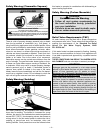
WARNING
Excessive Weight Hazard
Use two or more people to move and install
water heater. Failure to do so can result in
back or other injury.