


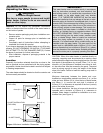
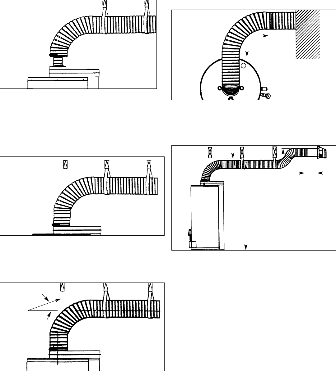
Figure 3G
Pull and connect the 80mm (3-1/8 in.) corrugated pipe to the
water heater’s flue tube reducer with hi-temp red silicone
and gear clamp. Make sure this connection is tight and leak
proof.
*The sealant between 80mm (3-1/8 in.) corrugated pipe and
water heater’s flue tube reducer must be hi-temp red sili-
cone or other material suitable for 315°C (600°F) continu-
ous service.
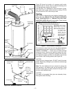
Figure 3H
Apply silicone around 152mm (6 in.) collar on air manifold
box. Pull corrugated vent tube all the way on to collar and
secure with one sheet metal screw (approx. 19mm (3/4 in.)
up from edge of vent tube. Pull gear clamp past screw and
tighten.
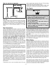
Figure 3J
Check the vent pipe’s level or slope again, and adjust if
required.
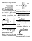
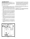
Offset vent pipe arrangement
Figure 3K - CONDITION 1
Where a straight vent pipe arrangement is impossible, a
horizontal 90 degree maximum bend can be made. Use the
water heater casing outer diameter as a template to form
the corrugated pipe.
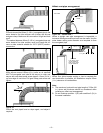
Figure 3L - CONDITION 2
Where floor joists impede venting, a rise to complete the
vent termination is possible. All installations require 25mm
(1 in.) clearance to combustibles.
Note:
A. The maximum horizontal vent pipe length of 2.28m (90
in.) minus wall thickness should be considered when
installing an offset vent arrangement.
B. Do not combine condition 1 (3K) with condition 2 (3L) in
the same installation.
– 8 –
SLOPE
TOP VIEW
90° MAXIMUM
BEND
WALL 254mm
(10 in.) (REF)
MINIMUM
1.72m (68 in.) FOR
40 gal. MODELS,
1.93m (76 in.) FOR
50 gal. MODELS.
>25mm (1 in.)
>25mm (1 in.)