


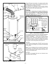

Temperature & Pressure Relief Valve
For protection against excessive pressure and/or tempera-
tures, a temperature and pressure relief valve has been
installed in the water heater.
ANY REPLACEMENT VALVE MUST NOT EXCEED THE
TEMPERATURE AND PRESSURE RATING. FAILURE TO
INSTALL AND MAINTAIN A NEW, PROPERLY LISTED
TEMPERATURE AND PRESSURE RELIEF VALVE WILL
RELEASE THE MANUFACTURER FROM ANY CLAIMS
WHICH MIGHT RESULT FROM EXCESSIVE TEMPERA-
TURE OR WATER PRESSURE.
Pressure rating of the valve must not exceed the working
pressure shown on the rating plate of the water heater. The
discharge capacity must be equal to or greater than the
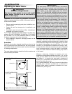
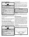
input to the water heater. Temperature and Pressure Relief
valve piping must terminate 152mm (6 in.), no more than
305mm (12 in.) (reference the applicable code) above a
floor drain or external to the building. Do not thread, cap, or
plug the end of this discharge line. Be certain that no con-
tact is made with any live electrical part. Do not connect dis-
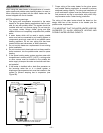
charge line directly to drain (see Figure 2A). To prevent bod-
ily injury, hazard to life or damage to property, the relief
valve must be allowed to discharge water in the event of
excessive temperature or pressure developing in the water
heater. The function of the temperature and pressure relief
valve is to discharge water in quantities should circum-
stances demand. If the discharge pipe is not directed to
drain as shown in Figure 2A, or other suitable means, the
water flow may cause property damage.
The discharge line:
1. must not be smaller than the outlet pipe size of the relief
valve,
2. must not be plugged or blocked,
3. must be material capable of withstanding 99°C (210°F)
without distortion,
4. must be installed so as to allow complete drainage of
both temperature and pressure relief valve,
5. must terminate at an adequate drain, and
6. must not have any valve between the relief valve and
the water heater.
Closed system/Thermal expansion
Periodic discharge of the temperature and pressure relief
valve may be due to thermal expansion in a closed water
supply system. The water utility supply meter may contain a
check valve, backflow preventer or water pressure-reducing
valve. This will create a closed water system. During the
heating cycle of the water heater, the water expands caus-
ing pressure inside the water heater to increase. This may
cause the temperature and pressure relief valve to dis-
charge small quantities of hot water. To prevent this, it is
recommended that a diaphragm-type expansion tank (suit-
able for potable water) be installed on the cold water supply
line. The expansion tank must have a minimum capacity of
5.6 litres (1.5 US gallons) for every 190 litres (50 US gal-
lons) of stored water and be rated at the working pressure
of the water heater. Contact the local water supplier or
plumbing inspector for information on other methods to con-
trol this situation.
Important: Do not plug or remove the temperature and
pressure relief valve.
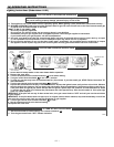
Installation Checklist
WARNING
Do not attempt to operate this water heater
with the cold water inlet valve closed.
Manually operate the Temperature and
Pressure Relief valve at least once a year.
Standing clear of the outlet (discharge water
may be hot), lift and release the lever handle
on the Temperature and Pressure Relief
valve to make the valve operate freely.
NEVER OPERATE THE HEATER IF IT IS NOT
COMPLETELY FILLED WITH WATER. TO
MAKE SURE THE HEATER IS FILLED, OPEN
A HOT WATER TAP UNTIL A FULL FLOW OF
WATER IS VISIBLE WITH NO AIR ESCAPING.
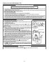
Check Here
1. Have the vent location limitations and minimum
height for vent termination and maximum vent
length been checked?
2. Are the terminal and vent pipes installed and
sealed properly?
3. Has the gas piping been leak tested?
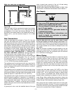
4. Is there 508mm (20 in.) at the top and 25mm (1
in.) around the vent pipe?
5. Have you taken steps to prevent water damage
in case of leaks?
6. Is the diptube installed in the cold water inlet
connection?
7. Is the water heater completely filled with
water?
8. Does the gas piping conform with the recom-
mendations of your Local Gas Utility
Company?
9. Is the vent terminal opening unobstructed?
10. Is a temperature and pressure relief valve
installed?
11. Is the drain pipe from the T&P valve unob-
structed?
12. Has all plastic and cardboard packaging mate-
rial been removed from the heater and vent-
ing?
If the answer to all of the questions above is
“Yes”, read the Operating Instructions and
proceed with lighting the heater.
– 10 –