


– 6 –
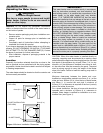
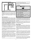
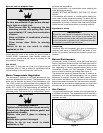
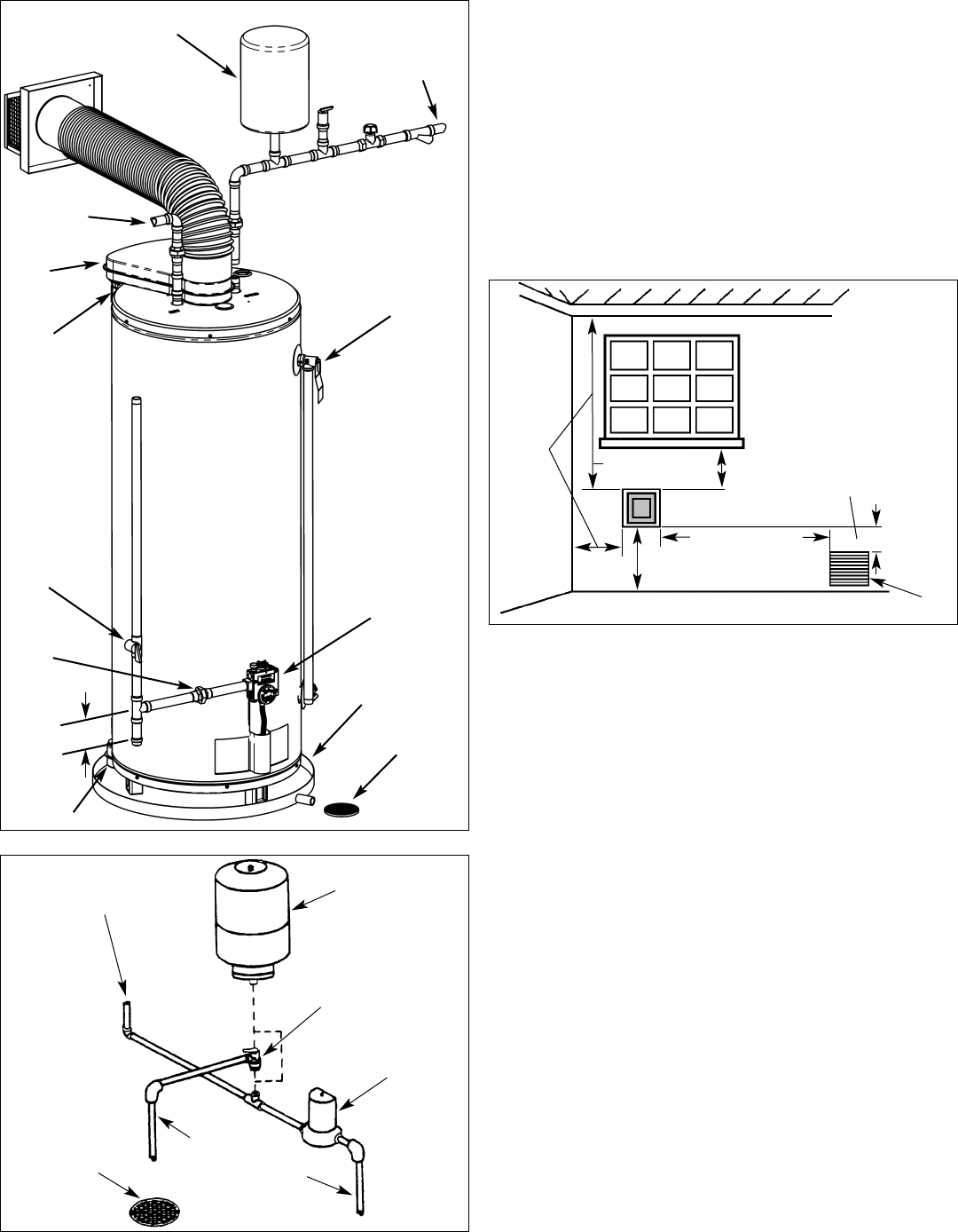
Figure 2A - Installation Components.
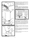
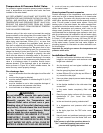
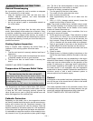
Figure 2B - Installation Options.
Figure 2B shows the location of a pressure relief and/or
expansion tank if a check valve or pressure-reducing valve
is in the cold water supply to the house.
Use OPTION 1 or 2 whichever is more convenient. If pres-
sure relief valve is used, select one with a setting 172 kPa
(25 psi) below the T&P valve rating at tank.
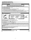
Venting
Make certain to observe the vent location limitations com-
plying with the "Natural Gas and Propane Installation
Code" CAN/CSA-B149.1 or "National Fuel Gas Code"
ANSI Z223.1 (NFPA 54) and/or local codes. There is some
important information shown in Figure 3.
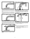
For a second or more direct vent unit, the distance between
vent terminals must have a minimum of 305mm (12 in.).
INSPECT SHIPMENT –– There may be hidden damage
caused by transit. Check to be certain all parts of the vent-
ing system, as shown in Figures 3A through 3M, are pres-
ent. Inspect the upper and lower air inlet boxes, rear air tube
and all parts of the venting system (see Figure 2A).
CAUTION
If there are any damaged parts, DO NOT install this water
heater. Report any shortage to your distributor and damage
to your carrier.
Note: The four fasteners that are required to secure the
vent terminal to the exterior wall are not provided. These
should be screw type (not nails) chosen for the type of con-
struction and obtained locally.
CAUTION
Cut edges of corrugated (flex) pipe are extremely sharp.
Wear gloves when handling.
OPTION 1
OPTION 2
SEDIMENT
TRAP
152mm (6 in.)
HOT WATER
OUTLET
GAS SUPPLY
MANUAL
SHUT-OFF
VALVE
GROUND-JOINT
UNION
FLOOR DRAIN
TEMPERATURE
& PRESSURE
RELIEF VALVE
COLD WATER
INLET
GAS CONTROL
UPPER AIR
INLET BOX
REAR AIR
TUBE
DRAIN PAN
EXPANSION TANK
WATER SUPPLY
TO HOME
WATER METER
WITH BACKFLOW
PREVENTER
PRESSURE
RELIEF VALVE
OVERFLOW
WATER SUPPLY
TO METER
FLOOR DRAIN
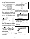
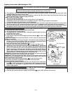
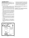
Figure 3 - Vent Location Limitations
Vent Terminal must be located at
least 305mm (12 in.) from
Windows, Doors, or any other
Opening through which flue
gases could enter the building.
Any Forced Air Inlet
into the building
Vent Terminal must be located at least 457mm
(18 in.) from any overhang or building corner
or other irregularity.
305mm (12 in.) Min.
above grade. Higher in
Areas of Heavy Snowfall
Within 1.8m (6 ft.)
915mm
(36 in.)
Min.
305mm
(12 in.)
Min.
Vent terminal must
be located at least
915mm (36 in.)
above any Forced Air
Inlet into the building
within 3m (10 ft.) of
the Vent Terminal
457mm (18 in.)
Min.
EXPANSION
TANK
LOWER AIR
INLET BOX