


– 31 –
VII) COMBO HEATING
This section serves as a guide for the installation and use of
"Combo" heating systems utilizing a domestic water heater
that has been specifically approved for such use. It is writ-
ten for those knowledgeable in the required trades and pro-
fessionals involved in the design and installation of Combo
Heating Systems.
It is the responsibility of the installer/designer to follow
all applicable codes to ensure the effectiveness and
safety of the installation.
System Requirements
The following requirements must be met for the installation
of Combo Heating Systems:
1. All components used for the distribution of water in the
heating loop must be suitable for potable water. These
include all piping, fittings, solder and fluxes, pumps for
circulation of water, valves, etc.
2. The water heater must not be connected to a hydronic
heating system that has been used previously.
3. No boiler treatment chemicals of any kind shall be intro-
duced into the system.
4. The Combo System components must be selected and
sized to meet and maintain the total calculated
demands for both domestic service hot water and space
heating requirement. The sizing and installation must be
performed in accordance with good engineering prac-
tice such as "ASHRAE Handbooks", HRAI,
"Hydronics Institute Manuals", CSA B149.1, NFPA
54, ANSI Z223.1, CSA F280, National/Provincial
Building Codes, CSA C22.1, ANSI/NFPA 70, CSA
B51 and/or codes having jurisdiction.
5. The air handler (fan coil) and/or the circulating pump in
a baseboard hydronic loop will require a dedicated
120V circuit. This must be provided and identified for
this purpose.
6. All piping between the water heater and the air handler
or hydronic baseboard loop must be adequately insulat-
ed to reduce heat loss.
7. If the local jurisdiction requires a back-flow preventer in
the cold water line, an expansion tank of adequate size
must be installed.
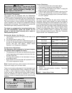
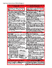
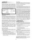
8. "Combo" Heating Systems require higher water temper-
atures than other applications. When the system is
used to supply water for Combo Heating applications, a
means, such as mixing valve, must be installed to tem-
per the water in order to reduce scald hazard potential
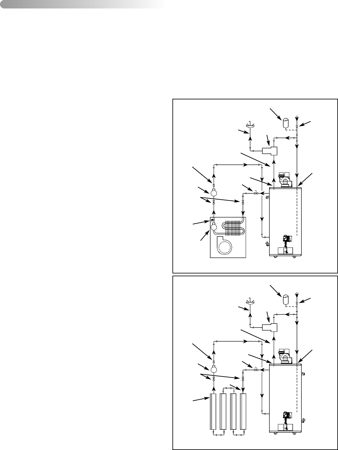
(see Figures 29 & 30).
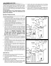
Installation
The heating mode may be one of the following options:
A. A fan coil/air handler (Figure 29).
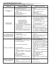
B. A hydronic baseboard (finned tube) loop/In floor heating
(Figure 30).
The following is a list of requirements for the installation of
the heating loop to the water heater.
1. Install shut-off valves and unions so that the water
heater can be isolated from the heating module should
servicing of the water heater become necessary.
2. Install a drain valve at the lowest point of the heating
loop so that water can be drained from the heating mod-
ule without affecting the water heater.
3. If the air handler does not have a venting means at the
highest point of the piping arrangement, install an air
bleed at the highest point of the plumbing arrangement.
WATER
HEATER
8in TO 12in
MAX.
HOT
OUTLET
EXPANSION TANK
(OPTIONAL)
MIXING
VALVE
COLD
INLET
CHECK VALVE
(IF USED
REQUIRES
EXPANSION
TANK)
COLD
SUPPLY
HOSE BIB
(OPTIONAL)
FLOW
CONTROL
SUPPLY
RETURN
CHECK
VALVE
EXTERNAL
CIRCULATOR
AIR HANDLER
HOT WATER
TO HOUSE
FIXTURE
C
H
M
INTERNAL
CIRCULATOR
DRAIN/PURGE
VALVE
Figure 29 Combo Heating - Air Handler
WATER
HEATER
8in TO 12in
MAX.
HOT
OUTLET
EXPANSION TANK
(OPTIONAL)
MIXING
VALVE
COLD
INLET
CHECK VALVE
(IF USED
REQUIRES
EXPANSION
TANK)
COLD
SUPPLY
HOSE BIB
(OPTIONAL)
FLOW
CONTROL
SUPPLY
RETURN
CHECK
VALVE
EXTERNAL
CIRCULATOR
HOT WATER
TO HOUSE
FIXTURE
C
H
M
HYDRONIC
BASEBOARDS
(SERIES CON-
NECTED
SHOWN)
Figure 30 Combo Heating - Baseboard