


Closed System/Thermal Expansion
Periodic discharge of the temperature and pressure relief
valve may be due to thermal expansion in a closed water
supply system. The water utility supply meter may contain a
check valve, backflow preventer or water pressure-reducing
valve. This will create a closed water system. During the
heating cycle of the water heater, the water expands caus-
ing pressure inside the water heater to increase. This may
cause the temperature and pressure relief valve to dis-
charge small quantities of hot water. To prevent this, it is
recommended that a diaphragm-type expansion tank (suit-
able for potable water) be installed on the cold water supply
line. The expansion tank must have a minimum capacity of
5.6 litres (1.5 US gallons) for every 190 litres (50 US gal-
lons) of stored water and be rated at the working pressure
of the water heater. Contact the local water supplier or
plumbing inspector for information on other methods to con-
trol this situation.
Important: Do not plug or remove the temperature and
pressure relief valve.
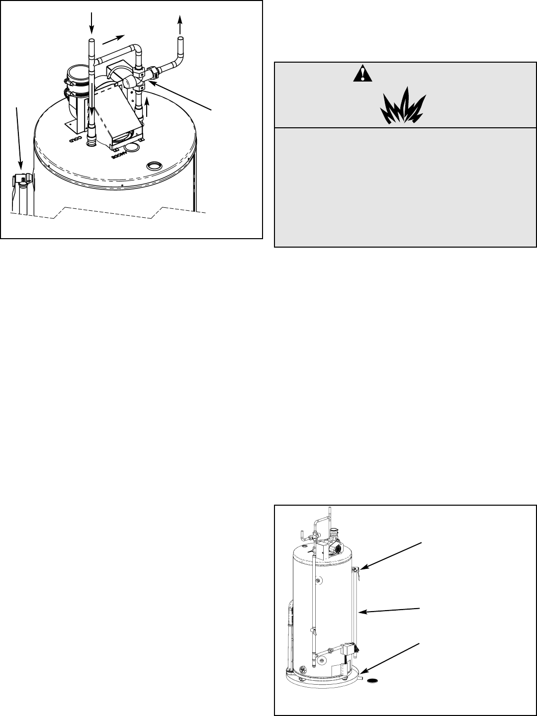
Temperature and Pressure (T&P) Relief
Valve
For protection against excessive pressures and tempera-
tures, a temperature and pressure relief valve must be
installed in the opening marked "T&P RELIEF VALVE" (see
Figure 18). This valve must be design certified by a nation-
ally recognized testing laboratory that maintains periodic
inspection of the production of listed equipment or materials
as meeting the requirements of the "Standard For Relief
Valves For Hot Water Supply Systems", ANSI
Z21.22/CSA 4.4. The function of the temperature and pres-
sure relief valve is to discharge water in large quantities in
the event of excessive temperature or pressure developing
in the water heater. The valve's relief pressure must not
exceed the working pressure of the water heater as stated
on the data plate.
Important: Only a new temperature and pressure relief
valve should be used with your water heater. Do not use an
old or existing valve, as it may be damaged or not adequate
for the working pressure of the new water heater. Do not
place any valve between the relief valve and the tank.
The Temperature and Pressure Relief Valve:
• Must not be in contact with any electrical part.
• Must be connected to an adequate discharge line.
• Must not be rated higher than the working pressure
shown on the data plate of the water heater.
The Discharge Line/Driptube:
• Must not be smaller than the pipe size of the relief valve
or have any reducing coupling installed in the discharge
line.
• Must not be capped, blocked, plugged or contain any
valve between the relief valve and the end of the dis-
charge line.
• Must terminate a maximum of 300mm (12 in.) (Canada)
or 150mm (6 in.) (U.S.A.) above the floor.
• Must be capable of withstanding 121°C (250°F) without
distortion.
• Must be installed to allow complete drainage of both the
valve and discharge line.
– 16 –
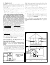
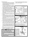
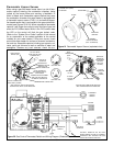
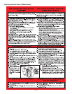
COLD
WATER
INLET
HOT
WATER
OUTLET
TEMPERING
VALVE (SET
TO 49°C
(120°F))
TEMPERED
WATER TO
FIXTURE
Figure 17 Tempering Valve Installation
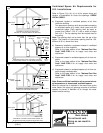
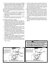
FOLLOW THE
TEMPERING
VALVE MANU-
FACTURER'S
INSTRUCTIONS
T&P VALVE
AND DIS-
CHARGE
LINE
COLD WATER
Figure 18 Temperature & Pressure Relief Valve
Installation
TEMPERATURE AND
PRESSURE RELIEF
VALVE
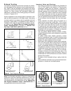
DISCHARGE LINE 19mm (3/4 in.)
MIN. DO NOT CAP OR PLUG.
DRAIN PAN. CONNECT TO
PROPERLY OPERATING
FLOOR DRAIN.
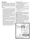
WARNING
Explosion Hazard
• If the temperature and pressure relief
valve is dripping or leaking, have a
licensed plumber repair it.
• Do not plug valve.
• Do not remove valve.
• Failure to follow these instructions can
result in death or an explosion.