


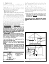
Venting instructions
1. Plan the venting layout starting at the vent termination
and work back toward the heater. Take into considera-
tion the style and position of the vent termination, the
vent pipe routing, elbows and connectors required and
the necessary support hangers.
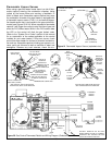
2. G/JW 40, 50 and 60-gallon heaters may use 50mm (2
in.) or 76mm (3 in.) venting depending on "Equivalent
Vent Length" as described in Table 2. G/JW5065 high
input models require 76mm (3 in.) venting. See also the
section on "Vent pipe connection to blower".
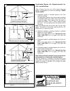
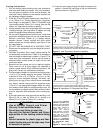
3. Venting should be as direct as possible with the fewest
number of fittings. Use long radius 45 degree and long
radius 90 degree elbows wherever possible.
4. Do not use 90 degree elbows "back to back" (other than
termination installations) and do not use street elbows.
Maintain a minimum 150mm (6 in.) straight section
between elbows. Closely coupled and short radius
elbows reduce the venting capacity (see Figure 6 and
the note below it).
5. DO NOT USE AN ELBOW AS A SUPPORT POINT.
Elbows are not designed to carry the weight of the vent-
ing system.
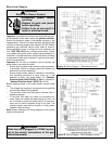
6. Calculate "Equivalent Vent Length" before starting. Do
not exceed the values shown in Table 2. An example of
how this length is determined is shown in Figure 8. The
value from your calculations should also be used to
determine which rodent screen to install into the vent
termination elbow.
7. Measure the vent piping and cut to required lengths.
Pipes must be cut at right angles and deburred to
ensure a good smooth fit with sufficient overlap for the
glue joints. Correct any interference conditions.
8. Provide support hangers for horizontal vent piping every
1.2m (4 ft.) to prevent sagging and stress. Provide a
minimum of 3mm (1/8 in.) rise per 1.2m (4 ft.) of vent
piping to ensure adequate drainage. Horizontal vent
piping must not sag to form valleys where condensate
may collect. Vertical venting shall be supported every
1.5m (5 ft.). Use appropriate support straps and vibra-
tion isolators (foam pads) on straight sections only. Do
not use elbows as support points. Allow sufficient clear-
ance for expansion and contraction of the venting sys-
tem.
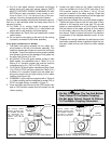
9. At the point where the vent pipe exits the building, cut a
65mm (2-1/2 in.) hole for 50mm (2 in.) venting or a
90mm (3-1/2 in.) hole for 76mm (3 in.) venting.
10. Insert the vent piping through this hole and secure into
position. Connect the vent pipe to the end termination
elbow as shown in Figures.9-11.
– 13 –
CAUTION:
Use of Solvent Cement and Primer
• Use only in well-ventilated areas.
• Do not use near flame or open fire.
• Use only the Solvent Cement and Primer
appropriate for the venting material being
used.
• Solvent cements for plastic pipe are flam-
mable liquids and must be kept away from
all sources of ignition.
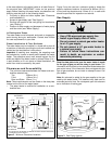
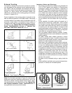
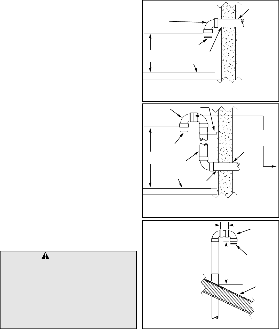
SEALANT
SEALANT
GROUND LEVEL
OR MAXIMUM
SNOW LINE*
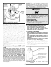
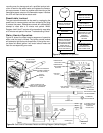
Figure 9 Vent Termination Exterior Installation
RODENT SCREEN
(INSTALL INTO
ELBOW)
* WHERE SNOW COVER IS NORMAL DURING WINTER, ENSURE
SUFFICIENT VENT CLEARANCE TO PREVENT BLOCKAGE OR ICE BUILDUP.
300mm
(12 in.)
MIN.
ATTACH 90°
TERMINATION
ELBOW
VENT PIPING MAY BE
SLOPED IN ANY
DIRECTION, AS LONG
AS A WATER TRAP IS
NOT CREATED IN
THE VENTING SYS-
TEM. THE SLOPE
SHOULD BE KEPT TO
A MINIMUM SO AS
NOT TO EXERT ANY
UNDUE STRESS ON
THE PIPE.
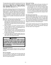
BRACKET
VENT
RISER
SEALANT
SEALANT
ATTACH 90°
TERMINATION
ELBOW
GROUND LEVEL
OR MAXIMUM
SNOW LINE*
Figure 10 Installation Of Fabricated Vent Riser.
RODENT
SCREEN
(INSTALL
INTO
ELBOW)
VENT PIPING TO BE
SLOPED (DOWN)
TOWARD HEATER TO
PREVENT WATER
FROM COLLECTING.
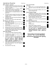
EQUIVALENT
VENT LENGTH
MEASURED FROM
THIS POSITION
* WHERE SNOW COVER IS NORMAL DURING WINTER, ENSURE
SUFFICIENT VENT CLEARANCE TO PREVENT BLOCKAGE OR ICE BUILDUP.
300mm
(12 in.)
MIN.
TERMINATION
MAY BE 90°
ELBOW
76mm (3 in.)
MIN. LENGTH
ROOF
LINE
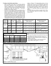
Figure 11 Vertical Venting
A VENT USED IN A SPECIAL
VENTING SYSTEM WITH
POSITIVE VENT PRESSURE
AND PASSING THROUGH A
ROOF SHALL EXTEND AT
LEAST 450mm (18 in.)
ABOVE THE HIGHEST
POINT WHERE IT PASSES
THROUGH THE ROOF SUR-
FACE AND ANY OTHER
OBSTRUCTION WITHIN A
HORIZONTAL DISTANCE OF
450mm (18 in.). A VERTICAL
VENTING SYSTEM MUST
BE SUPPORTED EVERY
1.5m (5 ft.).
RODENT
SCREEN
(INSTALL
INTO
ELBOW)
450mm
(18 in.)