


rounding area for damage and call a qualified service tech-
nician to service the water heater and replace the flamma-
ble vapour sensor. If there is a problem with the wiring of the
flammable vapour sensor or the flammable vapour interface
the LED will flash the failure status code.
Resettable Lockout
The gas control/thermostat can be reset by unplugging the
power cord to remove power and then reinserting the plug
to restore the power. Robertshaw controls will automatically
attempt to reset after a 20 minute wait period. White-
Rodgers Intelli-Vent™ controls will automatically reset after
a 60 minute wait period. Also see "Troubleshooting Guide".
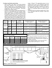
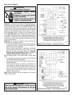
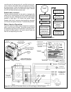
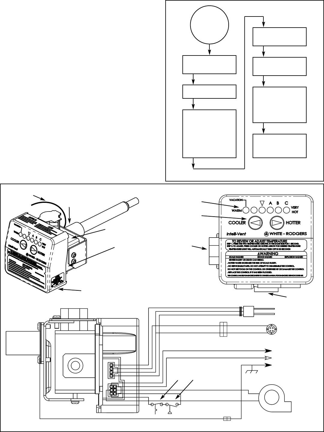
Water Heater Operation
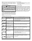
Figure 23 shows the water heater's sequence of operation
when a call for heat is initiated. The ignition control module
will attempt to light the burner three times. If the ignition con-
trol does not detect ignition it will enter lockout mode and
flash the corresponding error code.
– 19 –
CONTROL CHECKS TO
ENSURE PRESSURE
SWITCH IS OPEN
BLOWER IS
ENERGIZED
CONTROL CHECKS TO
ENSURE PRESSURE
SWITCH CLOSES
INDICATING BLOWER
IS OPERATING AND
THERE ARE NO
VENTING BLOCKAGES
(INLET OR OUTLET)
IGNITER IS
ENERGIZED AND MAIN
VALVE IS OPENED
MAIN BURNER ON AND
THE FLAME IS
SENSED BY CONTROL
MAIN BURNER
CONTINUES TILL THE
WATER IN THE TANK
REACHES
THERMOSTAT
SETTING
MAIN BURNER SHUTS
OFF. BLOWER
CONTINUES FOR A
POST PURGE TIME
CALL FOR
HEAT
Figure 23 Sequence Of Operation
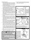
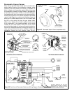
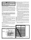
GAS CONTROL
SIDE VIEW
QUICK CONNECTS FOR
POWER SUPPLY AND IGNITER
LOCATED ON UNDERSIDE
OUTLET
PRESSURE
PORT
MANIFOLD PRESSURE
ADJUSTMENT (REMOVE
CAP FOR ACCESS)
3/4” NPT. WRAP
WITH TEFLON TAPE
(2 WRAPS MIN.)
GROUND
CONNECTION
GAS CONTROL
FRONT VIEW
GAS OUTLET
TO BURNER
GAS INLET
1/2” NPT
TEMPERATURE
ADJUSTMENT
BUTTONS
TEMPERATURE
INDICATORS
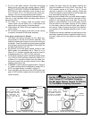
IGNITER AND FLAME
PROBE ASSEMBLY
FLAMMABLE
VAPOUR SENSOR
COMBUSTION
BLOWER
AIR
PRESSURE
SWITCH
HIGH
LIMIT
SWITCH
TO POWER SUPPLY
DISCONNECT AND
OVERLOAD
PROTECTION
WHITE
BLACK
CONNECTOR
GREEN
INTELLI-VENT
TM
CONTROL
BOTTOM VIEW
Figure 24 Gas Control/Thermostat Details and Wiring Diagram (White-Rodgers)
CONNECTOR
GREEN