11. Dry fit all vent pipes, elbows, connectors and fittings
before joining any parts with solvent cement. PARTS
MUST FIT WITHOUT STRESS OR BENDING OF ANY
SECTION and each connection must overlap a mini-
mum of 13mm (1/2 in.). Do not force fit any of the con-
nections. Use only the appropriate solvent cement.
Caution: Solvent cements may produce flammable vapours.
Use only in well-ventilated areas and keep away from all
sources of ignition.
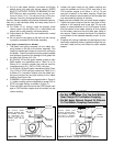
12. For 50mm (2 in.) venting, install the properly sized
rodent screen into the 50mm (2 in.) outlet elbow and
secure with a small quantity of silicone sealant.
13. Outlet elbows for 76mm (3in) are installed with a metal
rodent screen.
14. Do not seal the vent piping to the wall until the venting
is properly connected to the blower assembly.
Vent pipe connection to blower
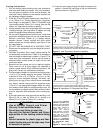
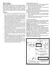
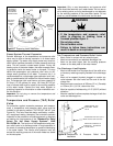
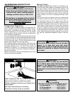
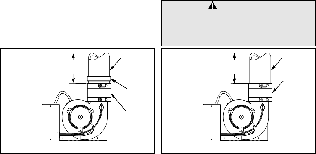
1. The plastic vent piping connects into the rubber cou-
pling located on the top of the blower assembly. This
coupling includes gear clamps to connect the venting to
the blower. These connections must be properly seated
and tightened to prevent the leakage of flue gases into
the area. See Figures 15 & 15a.
2. All G/JW 40, 50 and 60 gallon models, except hi-input
5065 models, are assembled with a 76mm (3 in.) to
50mm (2 in.) transition coupler that must be used for
installations using 2 in. PVC or CPVC vent pipe.
3. For G/JW 40, 50 and 60 gallon installations using 76mm
(3 in.) PVC or CPVC vent pipe, remove the 76mm (3 in.)
to 50mm (2 in.) transition coupler from the rubber cou-
pling and connect the vent pipe directly to the rubber
coupling. See Figure 15a.
4. G/JW5065 hi input models are supplied with a 76mm (3
in.) rubber coupling and are designed to accept PVC or
CPVC vent pipe directly, as shown in Figure 15.
5. Clean and lightly sand the end of the CPVC plastic vent
pipe or PVC transition coupler that will connect into the
rubber coupling.
6. Loosen the upper clamp on the rubber coupling and
insert the sanded end of the CPVC vent pipe or the
PVC transition coupler a full 32mm (1-1/4 in.). Do not
use glue or sealant in the rubber coupling. Check that
there is no stress on the connection or the vent pipe that
may be caused by twisting or bending.
* These parts are available from your water heater supplier.
7. Tighten the upper clamp so that the vent pipe is firmly
secured in the coupling and is gas tight. Do not over
tighten or cause distortion of any of the parts. Ensure
that the bottom of the rubber coupling is firmly seated
on the blower outlet and that the lower gear clamp is
also secure. Check to ensure that there is no distortion
or movement of the clamped assembly once it is com-
pleted.
8. Complete the venting installation by sealing around the
termination assembly where it passes through the out-
side wall, inside and out, with silicone or other suitable
sealant.
– 14 –
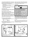
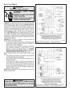
CAUTION:
• Do Not Overtighten The Top And Bottom
Gear Clamps Of The Rubber Coupling.
• Do Not Apply Solvent Cement Or Silicone
To The Rubber Coupling Connection.
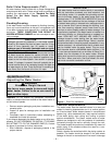
Figure 15 Blower, Fittings and Vent Pipe Options
HI-INPUT MODEL 5065
HEATERS. BLOWER ASS’Y
WITH RUBBER COUPLING
FOR 76mm (3 in.) NOMINAL
CPVC OR PVC VENT PIPE.
150mm (6 in.)
MIN. TO 1
ST
ELBOW
VENT PIPE
76mm (3 in.)
RUBBER
COUPLING
Figure 15a Blower, Fittings and Vent Pipe Options
NON HI-INPUT MODEL
HEATERS. BLOWER ASS’Y
WITH RUBBER COUPLING
AND TRANSITION COU-
PLER FOR 50mm (2 in.)
NOMINAL CPVC OR PVC
VENT PIPE.
150mm (6 in.)
MIN. TO 1
ST
ELBOW
VENT PIPE
50mm (2 in.)
RUBBER
COUPLING
TRANSITION
COUPLER


