


9309098
Operation
Pressure Relief Procedure
WARNING
INJECTION HAZARD
To reduce the risk of serious injury, in-
cluding fluid injection or splashing in the
eyes or on the skin, always follow the
Pressure Relief Procedure whenever you
D Are instructed to relieve the pressure
D Shut off the pump
D Check, clean, or service any of the system
equipment
D Install or clean the dispensing devices
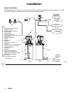
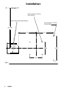
1. Disable hydraulic supply to pump (Fig. 2, item D)
by isolating it it from the high pressure hydraulic
supply using ball valve (AA).
2. Do one of the following:
D Open the pressure reducing valve to reduce
trapped hydraulic pressure,
or
D Cycle the timer to open the 3–way solenoid
valve to reduce trapped hydraulic pressure.
Note: Gage on control module should read zero
pressure after performing this step.
3. Disconnect power from Lubrication Controller (J).
WARNING
MOVING PARTS HAZARD
Do not insert finger into the overflow port
while filling a reservoir equipped with a
follower plate. Injury or amputation could
result.
Start-up
Prime Vent Line. The first time the reservoir is filled,
use the vent valve outlet. This removes all air from the
vent line (Fig. 2, item V).
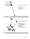
1. Connect lubricant supply hose from remote filling
station pump unit to outlet of vent valve (U).
2. Remove plug in fill port (K) located at bottom of
reservoir.
3. Slowly turn on supply lubricant until lubricant
appears in fill port.
4. Remove lubricant supply hose from vent valve.
Fill Reservoir
1. Connect lubricant supply hose from remote filling
station pump to fill port (Fig. 2, item K).
2. Connect automatic lube system main supply
line (G) to vent valve (U) outlet.
3. Remove plug from overflow port (L).
4. Slowly turn on supply lubricant until level of lubri-
cant reaches overflow port.
Note: For systems with a follower plate, fill until the
follower plate reaches the overflow port.
Note: Refer to Automatic Lube System Design Guide-
lines Manual 309015 for instructions on priming re-
maining system lubricant lines and further operating
instructions.
COMPONENT RUPTURE HAZARD
The maximum working pressure of each
component in the system may not be the
same. To reduce the risk of
overpressurizing any component in the system, be
sure you know the maximum working pressure of
each component. Never exceed the maximum
working pressure of the lowest rated component in
the system. Overpressurizing any component can
result in rupture, fire, explosion, property damage,
and serious injury.
Regulate hydraulic pressure to the pump so that no
fluid line, component, or accessory is
overpressurized.
WARNING
5. Set hydraulic pressure to pump at lowest pressure
needed [between 600 psi (41 bar, 4.1 MPa) and
1200 psi 83 bar, 8 MPa)] to get desired output
results [between 2500 psi (172 bar, 17 MPa) and
3500 psi (241 bar, 24 MPa)].
6. Set hydraulic flow rate to pump at lowest flow rate
needed to get desired results.
7. Read and follow instructions supplied with each
system component.
Note: With a primed pump and sufficient hydraulic
supply, the pump starts when the timer activates the
solenoid valve. The pump stops when the timer deacti-
vates the solenoid valve.