


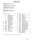
7309098
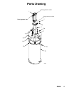
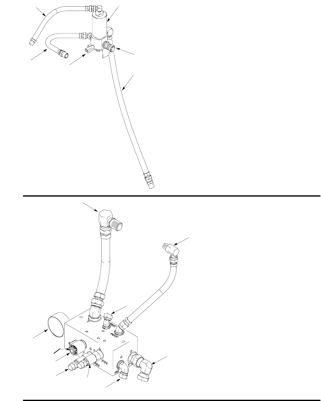
Fig. 3
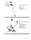
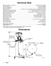
Vent Valve Installation Kit (243170)
KEY
A Hydraulic control line
B Vent valve
C Pump output connection line
D Pressure relief valve
E Lubricant output
F Vent line
A
9647A
B
C
D
E
F
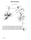
Fig. 4
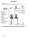
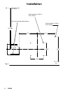
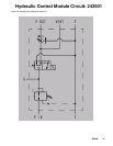
Control Module Installation Kit (243501)
KEY
G Pump tank line
H Pump high pressure hydraulic line
J Vent valve hydraulic control
K Hydraulic tank connection
L High pressure hydraulic connection
M Pressure reducing valve
N Flow control valve
P 3–Way solenoid valve
R Regulated hydraulic pressure gauge
*
Coil should always be installed with lettering facing out
G
9648A
H
J
K
L
N
P
M
R
*