


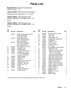
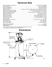
6 309098
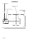
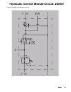
Installation
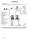
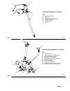
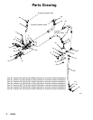
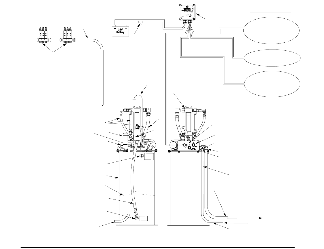
Typical Installation
The installation shown in Figs. 2, 4, and 5 are only a guide for selecting and installing system components. Contact
your Graco distributor for assistance in planning a system to suit your needs.
Fig. 2
Low Reservoir
Level Switch
(Level Indicator,
optional)
Pressure Switch
For System Control
Remote Alarm Device
(Light or Horn)
(User provided)
Controller
Capabilities
KEY
A High pressure hydraulic lines
B Hydraulic tank line
C Lubricant output connection
D Pump module
E Ignition switch*
F 3–Way solenoid valve
G High-pressure lubricant supply lines*
H Injector banks*
J Lubrication controller*
K Fill port
L Overflow port
M Breather
N Flow control valve (FCV)
P Reservoir
R Ground wire
(for non–mobile installation)*
S Pressure reducing valve (PRV)
T Hydraulic tank line*
U Vent valve
V Vent line
W Follower plate (optional)
X High pressure hydraulic line*
Y High pressure hydraulic connection
Z Tank hydraulic connection
AA Ball valve*
AB Level Indicator (optional)
* User provided
D
G
H
J
E
K
L
M
P
R
U
V
W
Front Back
A
G
B
F
N
S
T
X
9649B
C
Y
Z
AA
Hydraulic
Reservoir
Return
From Hydraulic
Power Supply
AB