


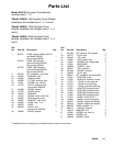
5309098
Installation
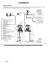
Reservoir
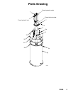
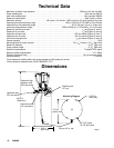
Mount reservoir [Fig. 2, item (P)] on sturdy flat surface
with 6, 3/8 in. diameter bolts. Note location of fill port
(K), hydraulic lines, and lubricant outlet port (G) for
easy access once installed.
Hydraulic system must depressurized before
connecting high pressure hydraulic supply line.
WARNING
CAUTION
Hydraulic supply must be 10μ filtered or better and
supply 0.5 – 3.0 gpm (1.9 – 11.4 lpm) at 800 psi –
3500 psi (55 bar – 241 bar, 5.5 MPa – 24 MPa).
1. Read instruction manual 308156 (included) before
installing this product.
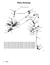
2. Install ball valve (Fig. 2, item AA) (user provided)
in the 3/8” hydraulic supply line ( X).
3. Connect the 3/8” hydraulic supply line (X) to the
swivel (Y).
4. Connect the 3/4” hydraulic tank line (T) to the
swivel (Z).
5. Connect the 24 VDC timer controlled signal to
the 3–way solenoid valve (F).
6. Connect supply line (G) to the lubricant swivel (C).
7. Ground system (see Grounding below). Mount
reservoir to grounded chassis member.
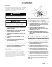
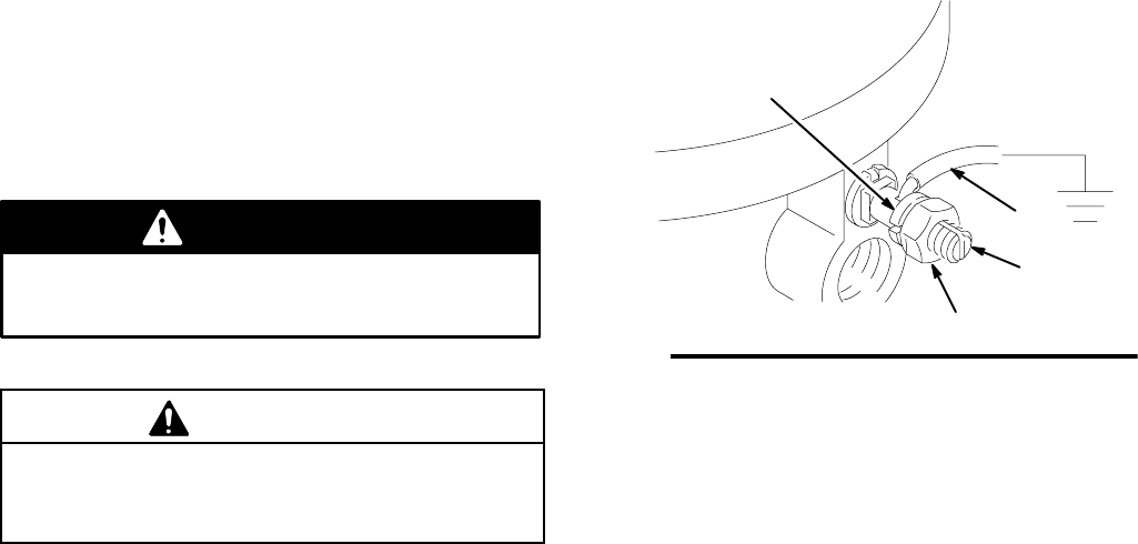
Grounding (for non–mobile installation)
Loosen grounding lug locknut [Fig. 1 item (A)] and
washer (B). Insert one end of a 12 ga (1.5 mm@)
minimum ground wire (C) into slot in lug (D) and
tighten locknut securely. Connect other end of wire to
true earth ground. To order a ground wire and clamp,
order part number 222011.
0720
Fig. 1
C
A
B
D
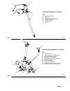
Vent Valve Kit for Custom Tank (Part
Number 243170) Installation (See Figure 3)
1. Weld the bracket (see Fig.5 ) in place per recom-
mended configuration for mounting the vent valve .
Paint the bracket if desired.
2. Connect the hydraulic control line (Fig. 3,
item A) to the control module vent valve hydraulic
control line (Fig. 4, item J).
3. Connect the high pressure lubricant line (Fig. 3,
item C) feeding the injector system to the lubricant
output (E).
4. Connect the vent line (F) to the lubricant reservoir.
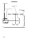
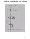
Control Module Kit for Custom Tank (Part
Number 243501) Installation (See Figure 4)
1. Mount the control module on a flat, sturdy surface
per the recommended configuration (see Fig.2 )
2. Connect the hydraulic tank line (Fig. 4, item G) to
the pump hydraulic outlet port.
3. Connect the vent valve hydraulic control (J) con-
nection to the hydraulic control line (Fig. 3, item A).
4. Connect the pump high pressure hydraulic line
(Fig. 4, item H) to the pump hydraulic input port.
5. Connect the high pressure hydraulic supply to the
high pressure hydraulic supply connection (L) and
the tank lines to the hydraulic tank connection (K).
6. Connect the 3–way solenoid valve (P) to the timer.
Note: Coil should always be installed with lettering
facing out.