


7307906
Installation
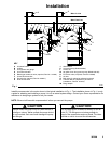
D Wall Bracket: Use the wall bracket (J) for w all
mounting the Universal pump. This wall br acket is
sized to fit any Graco pump designed to us e a 2-in.
bung adapter. Order Part No. 203987.
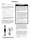
D Runaway Valve: Install a pum p runaway v alve to
shut off the air t o t he pump when the pump a cceler-
ates beyond the p re-adjuste d setting. A pump that
is in a runaway condition can be seriously dam-
aged.
Never allow the pump to r un dry of the fluid being
pumped. A dry pump quickly accelerates to a high
speed, possibly damaging itself, and it may get
very hot.
CAUTION
D Bleed-Ty pe Master Air Valve: Install a bleed-type
master air valve ( E) to r elieve air trapped between it
and the m otor when t he valve is closed. To order a
300 psi (2.1 MPa, 21 bar), 1/4-in. npt(f) bleed-type
master air valve, order Part No. 110223.
D Suction Kit: The suction kit (L) is for u se with the
wall-mounted Universal pump, and it includes a
drum tube and hos e. To order a suction k it, order
Part No. 213099.
D Air M otor Lubricator: The air motor lubricator (D)
provides automatic air motor lubrication. To order a
250 psi (1.7 MPa, 17.4 bar) 1/4-in. npt(f) a ir m otor
lubricator, order Part No. 110148.
D Air Regulator and Gauge: Use the air regulator and
gauge (C) to c ontrol air pr essure and pump speed.
To order a 0 to 200 psi ( 0 t o 1.4 MPa, 0 t o 14 bar)
regulated pressure range ( 300 psi [ 2.1 MPa,
21 bar] maximum), 1/4-in npt(f) air regulator and
gauge, order Part No. 110147.
D Air Filter: The air filter (B) removes harmful dirt and
moisture from the c ompressed air supply. To order
a 300 psi (2.1 MPa, 21 bar), 1/4-in npt(f) air filter
(20-micron element), order P art No. 110146.
D Air and Fluid Shutoff Valves: Install air shutoff
valves (A) and fluid s hutoff valves (H) as shown to
isolate the pump w hile you are servicing it.
D Quick-Disconnect Coupler and Nipple: The quick-
disconnect c oupler and nipple (not shown) are used
to quickly disconnect the air supply. A ttach the
coupler (Part No. 208536) to the pump air inlet
hose, and install the nipple (Part No. 169970) to the
pump air inlet (P).
D Thermal Relief Kit: Install t he thermal relief kit on
the dispensing valve side of the pump to assist in
relieving pressure in the pump, hose, and dis pens-
ing valve due to heat expansion. To order a 600 psi
(4.2 MPa, 41 bar) Thermal R elief Kit, order Part No.
237601.