


6 307906
Installation
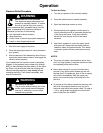
Grounding
Proper grounding is an essential part o f maintaining a
safe system.
To reduce the r isk of s tatic sparking, ground the pump.
Check your local e lectrical code for detailed grounding
instructions for your area and type of equipment. Be
sure to ground all of this equipment:
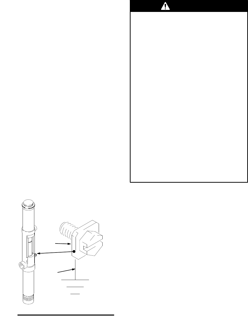
D Pump: Us e a ground wire and clamp as s hown in
Fig. 2.
D Air c ompressor: Follow the manufacturer’s recom-
mendations.
D Object being dis pensed to: Follow the local c ode.
D Fluid s upply c ontainer: Follow the local c ode.
D To maintain grounding continuity when flushing or
relieving pressure, alway s hold a metal part of the
dispensing valve firmly to the side of a grounded
meta l container , then trigger the valve.
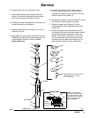
To ground the pump, remove the ground screw (Z)
and insert through the eye of the r ing terminal at end of
ground wire (Y). Faste n t he ground s crew back onto
the pump and tighten securely. Connect the other end
of the wire to a true earth ground. To order a ground
wire and clamp, order Part No. 222011.
Y
Z
05941B
Fig. 2
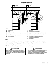
System Accessories
Three a ccessories are required in your system:
bleed-type master air valve, fluid drain v alve, and
grounding wire. Additionally, for per manent installa-
tions, a thermal relief kit is required. These acces-
sories help reduce the r isk of serious bodily injury,
including fluid injection, splashing in the eyes or on
the skin, injury from moving parts if you are adjus t-
ing o r r epairing the pump, and explosion from
static sparking.
D The bleed-type master air valve ( E) relieves air
trapped between it and the air motor after the
air supply is s hut off. Trapped air can c ause the
air motor to cycle unexpectedly, causing serious
injury if you are adjusting or r epairing the pump.
As an alternative, use a quic k-disconnect
coupler and fitting. In stall them near the pum p
air inlet within easy reach from the pump.
D The fluid drain v alve ( N) assists in r elieving fluid
pressu re in the displacement pump, hoses, and
dispensing valve. T riggering the valve to relieve
pressu re m ay not be sufficient.
D The ground wire (G) reduces the risk of static
sparking.
D The thermal relief kit (R) assists in r elieving
pressu re in the pump, hose, and dispensing
valve due to heat expansion.
WARNING
D Extension Tubes : Pump m odels 222103 and
222104 have extensions tubes. An extension tube
may be added to the Universal pump for use in
submerged applications. To i nstall, apply PTFE
tape to the female threads at the top of the tube.
Thread the tube tightly into the i ntake housing of
the Universal pump. Also, install a bung adapter. To
order a standard 2-in. bung adapter, order Part No.
222308.
D Air and Fluid Hose Kits (F): An 18-in. kit for wall-
mounted pumps and a 6-ft. kit for drum-mounted
pumps are available. Use a minimum 1/4-in. ID air
supply hose between the pump air inlet and the air
accessories. To order a kit with 1/4- in. air hose,
1/4- in. swivel elbow, 3/4-in. fluid hose, and 3/4-in.
swivel elbow, order one of the kits below:
222118 18-in. (0.4 m) hos e kit for w all-mounted
pumps
222119 6-ft (1.8 m) hose kit for d rum-mounted
pumps