


5307906
Installation
F
B
CD
E
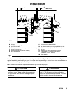
KEY
A Air shutoff valve
B Air filter
C Air regulator and gauge
D Air motor lubricator
E Bleed-type master air valve (required, Part No. 110223)
F Air and fluid hose kits
G Ground wire (required, Part No. 222011)
H Fluid shutoff valve
Main Air Line
Main Fluid Line
A
A
G
G
H
J
K
L
M
J Wall bracket
K Universal pump (Model 222051)
L Suction kit
M 55-gallon drum bung-mount pump (Model 222103)
N Fluid drain valve (required, Part No. 210658)
P Air inlet
Q Ball valve (for releasing collected moisture)
R Thermal relief kit (required for permanent
installations, Part No. 237601)
28 Bung adapter
Fig. 1
B
C
D E
F
N
N
P
P
28
Q
Q
R
H
R
05942B
Install the accessories in the o rder shown in t he t ypical i nstallation in Fig. 1. The installation shown in F ig. 1 is only
a guide for s electing and installing a pump; it is not an actual system design. Contact your Graco representative for
assistance in designing a system to suit your needs.
NOTE: Blow out all lines with compressed air before you connect the pumps.
Always mount the pump firmly to a wall bracket or
a bung on a d rum. Never operate the pump while it
is not mounted. Such use c ould damage the pump
and fitti ngs.
CAUTION CAUTION
Do not hang the air accessories directly on the air
inlet (P). The fittings are not strong enough to
support the accessories and may break. Provide a
bracke t o n which to mount the a ccessories.