


8 307-809
Installation
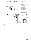
(Air-Powered Pumps)
Air Line to Motor
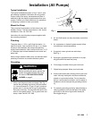
WARNING
A
bleed-type master air valve (D) is required in
your system, to help reduce the risk of serious
injury including splashing fluid in the eyes or on the
skin, and injury from moving parts if you are adjust
-
ing or repairing the pump.
The bleed-type master air valve relieves air trapped
between this valve and the pump after the air is
shut of
f. T
rapped air can cause the pump to cycle
unexpectedly
. Locate the valve close to the pump.
Order Part No. 1
13–333.
1.
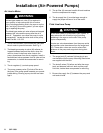
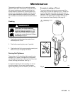
The air line lubricator (N) automatically lubricates
the air motor to prevent corrosion. See Fig. 2.
2.
The bleed-type master air valve (M) relieves air
trapped between itself and the motor
, when the
valve is closed. Install one valve close to the
pump, downstream from the air regulator
. Install a
second bleed valve upstream from all other air line
accessories, to isolate the accessories for servic
-
ing.
3.
The air regulator (L) controls pump speed.
4.
The pump runaway valve (P) shuts of
f the air to
the pump if the pump speed exceeds your pre-ad
-
justed setting. Running a pump too fast can dam
-
age it.
5.
The air filter (K) removes harmful dirt and moisture
from the compressed air supply
.
6.
The air supply line (J) must be large enough to
supply the proper volume of air to the motor
.
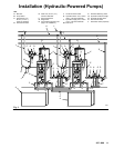
Fluid Line from Pump
WARNING
A
fluid drain valve (J) is required in your system, to
help reduce the risk of serious injury including
splashing in the eyes or on the skin if the pump
cycles unexpectedly
.
Locate one valve downstream from the pump outlet
and another valve downstream from the surge tank
(G). These drain valves are used to relieve fluid
pressure in the pump and surge tank during shut
-
down.
1.
The surge tank (G) reduces fluid surging to pre
-
vent backflow into the pump. Mounting instructions
are supplied with the tank.
2.
The shutoff valves (D) before and after the surge
tank, and between each mix tank and the pump
fluid inlet, isolate these components for servicing.
3.
Be sure the supply line (C) between the pump and
mix tanks is level.