


20 307-809
Service
Repair Kits
A
pump seal kit is available for each pump size. Throat
packing kits are also available, one for UHMWPE/
leather pumps and one for
PTFE pumps. The piston
seals may also be converted to PTFE. Refer to page
36 for ordering.
Parts supplied in the pump seal kit are marked with
one asterisk in the text and drawings, for example (2*).
Parts supplied in the throat packing kit are marked with
a symbol, for example (19
{
). For the best results, use
all the parts in the kit.
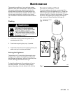
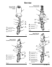
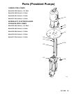
Disassembling the Displacement Pump
1. Remove
the pump from the motor as explained on
page 18.
2.
Secure the displacement pump intake housing (10)
in a vise.
3.
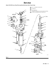
Refer to Fig. 9. Remove the four capscrews (9)
and washers (8) from around the pump outlet
housing (22).
4.
Remove the outlet housing (22), balls (23), seats
(24) and gaskets (7).
5.
Remove the three tie bolts (13) and lockwashers
(14). Lift of
f the upper pump housing (1), along
with the fluid tubes (3), cylinder (4), and piston
assembly (16).
6.
Remove the packing nut (21), glands (19, 26) and
packings (20, 25) from the upper housing (1).
NOTE:
Model 237–220 and 237–221 displacement
pumps use 5
PTFE v-packings in the throat, instead of
3 UHMWPE (20) and 2 leather (25).
7.
Remove the tubes (3) and cylinder (4) from the
housing.
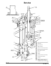
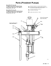
8.
Remove the intake housing (10) from the vise.
9.
Remove the four capscrews (9) and washers (8)
from the intake housing (10). Use a flatblade
screwdriver inserted between the lower pump
housing (1
1) and the intake housing (10) to sepa
-
rate the parts.
10.
Remove the balls (5), seats (6 and 32) and gas
-
kets (7).
NOTE:
One of the seats (32) has a vent hole. T
ake
note of the side of the pump in which this seat is used
(the left side when viewed as shown in Fig. 9).
WARNING
COMPONENT RUPTURE HAZARD
The vented ball seat (32) must be in
-
stalled at the fluid inlet. This valve
relieves pressure trapped in the pump
cylinder when the pump is shut of
f, and reduces
the risk of pump overpressurization. The seat
cannot relieve pressure if installed in any other
position.
NOTE:
Inspect the parts of the piston assembly (items
12, 15 and 16) in place before disassembling the
piston. The piston seal (15) is included in the Seal
Repair Kit. If it or any other parts of the piston show
wear or damage, proceed to step 1
1. If no damage is
apparent, it is not necessary to disassemble the piston.
11.
Place the flats of the piston nut (12) in a vise.
Unscrew the rod (17) from the nut. Disassemble
the two halves of the piston (16) and remove the
seal (15).
Cleaning and Inspecting Parts
Clean
all parts in a compatible solvent. Inspect all
parts for wear or damage. If you are using a repair kit,
use all the new parts in the kit, discarding the old ones
they replace. Replace any other parts as needed.
W
orn or damaged parts may cause the pump to per
-
form poorly or cause premature wear of the new seals
and packings.