


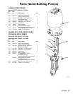
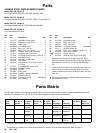
26 307-809
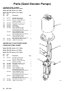
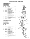
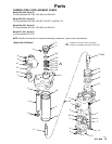
Parts
(President Pumps)
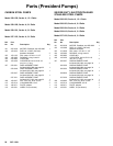
Model
220–574, Series B
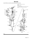
3:1 Ratio Carbon Steel President Pump,
with 55 gal. drum cover and agitator
Ref Part
No. No. Description Qty
201 220–561 PUMP,
President
See page 24 for parts
1
202 237–309
COVER, drum, 55 gal. (200 liter)
See 308–466 for parts
1
203 222–698 AGITATOR
See 306–840 for parts
1
204 220–580 RISER TUBE KIT
See 307–837 for parts
1
205 223–180 AIR REGULATOR KIT
Includes items 205a–205c
1
205a 203–716 REGULATOR, air
See 308–167 for parts
1
205b 205–418
HOSE, air; buna-N; 1/2” ID;
coupled 1/2 npt (mbe); 6 ft (1.9 m) lg
1
205c 158–491
NIPPLE; 1/2 npt
1
206 223–319 RETURN TUBE KIT
Includes items 206a–206d
1
206a 185–393
TUBE, return; sst; 1” npt(m)
1
206b 178–941 NUT
, hex; 1–5/8–18 unef–2b
1
206c 185–394 ADAPTER, return;
1–5/8–18 unef–2a(m) x
1” npt(f) x 1” npt(f)
1
206d 108–761 ELBOW
, street; 1” npt (m x f)
1
207 185–466
NIPPLE, half; 1–1/2” npt
1
208 100–839 ELBOW
; 1/8 npt (m x f)
1
Model
220–575, Series B
3:1 Ratio Stainless Steel President Pump,
with 55 gal. drum cover and agitator
Ref Part
No. No. Description Qty
201 220–564 PUMP,
President
See page 24 for parts
1
202 237–309
COVER, drum, 55 gal. (200 liter)
See 308–466 for parts
1
203 222–698 AGITATOR
See 306–840 for parts
1
204 220–580 RISER TUBE KIT
See 307–837 for parts
1
205 223–180 AIR REGULATOR KIT
Includes items 205a–205c
1
205a 203–716 REGULATOR, air
See 308–167 for parts
1
205b 205–418
HOSE, air; buna-N; 1/2” ID;
coupled 1/2 npt (mbe); 6 ft (1.9 m) lg
1
205c 158–491
NIPPLE; 1/2 npt
1
206 223–319 RETURN TUBE KIT
Includes items 206a–206d
1
206a 185–393
TUBE, return; sst; 1” npt(m)
1
206b 178–941 NUT
, hex; 1–5/8–18 unef–2b
1
206c 185–394 ADAPTER, return;
1–5/8–18 unef–2a(m) x
1” npt(f) x 1” npt(f)
1
206d 108–761 ELBOW
, street; 1” npt (m x f)
1
207 185–466
NIPPLE, half; 1–1/2” npt
1
208 100–839 ELBOW
; 1/8 npt (m x f)
1
Assembly
Procedure
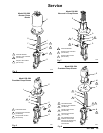
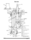
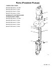
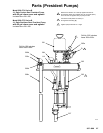
1. Screw
the half nipple (207) into the pump’
s fluid
inlet. Refer to the parts drawing on page 27.
2.
Remove the four nuts and lockwashers from the
posts of the drum cover (202) and save them for
use in step 3.
3.
Install the President pump (201) through the hole
in the drum cover (202). The four posts on the
drum cover must engage the four holes in the
pump adapter plate (1
14), and the notch in the
drum cover hole must align with the large hole in
the pump adapter plate. Secure the pump to the
drum cover with the lockwashers and nuts re
-
moved in step 2.
4.
Install the agitator (203) on the drum cover (202),
using the screws, washers and nuts supplied with
the drum cover
.
5.
Assemble the riser tube kit (204) to the pump
adapter plate (1
14) and pump fluid outlet (A) as
described in the separate kit manual, 307–837.
6.
Remove the 1/2 x 3/8 npt nipple from the outlet of
the air regulator (205a). This nipple will not be
used.
7.
Screw the 1/2 npt nipple (205c) into the outlet of
the air regulator (205a), then install the regulator
assembly into the pump’
s air inlet. Connect the air
hose (205b) to the swivel inlet (B) of the air regula
-
tor.
8.
Insert the male end of the return adapter (206c) in
the outermost hole of the drum cover
. Secure the
adapter to the underside of the cover with the hex
nut (206b).
9.
Screw the return tube (206a) up into the adapter
(206c). Install the street elbow (206d) in the adapt
-
er.
10.
Install the pump/cover/agitator assembly on a 55
gal. (200 liter) drum. Connect the air
, fluid, and
return lines.