


10 307-809
Installation
(Hydraulic-Powered Pumps)
Hydraulic Power Supply
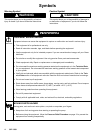
CAUTION
The
Hydraulic Power Supply must be kept clean at
all times to avoid damage to the motor and hydraulic
power supply
.
1.
Blow out hydraulic lines with air and flush thor
-
oughly before connection to the motor
.
2.
Plug hydraulic inlets, outlets, and line ends when
disconnecting them for any reason.
1.
Be sure the power supply can provide suf
ficient
power to the motor
.
2.
Be sure the power supply is equipped with a
suction filter to the hydraulic pump.
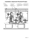
Hydraulic Supply to Motor
NOTE:
The motor’
s hydraulic inlet is 3/4 in., 37
_
flare.
Use a minimum 13 mm (1/2 in.) ID hydraulic supply
line (L).
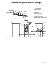
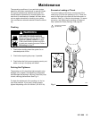
1.
The shutof
f valve (R) isolates the motor when
servicing the system. See Fig. 3.
2.
The hydraulic fluid pressure gauge (Q) monitors
the hydraulic oil pressure to the motor
. This helps
avoid overpressurizing the motor or displacement
pump.
3.
The pressure- and temperature-compensated flow
control valve (S) prevents the motor from running
too fast, which can damage it.
4.
The pressure reducing valve (P) which has a drain
line (M) running to the return line (K), controls the
hydraulic pressure to the motor
.
Hydraulic Return from Motor
NOTE: The motor’
s hydraulic outlet is 7/8 in., 37
_
flare. Use a minimum 16 mm (5/8 in.) ID hydraulic
return line (K).
1.
The shutof
f valve (R) isolates the motor when
servicing the system.
CAUTION
T
o avoid damage to the pump, never use the return
line shutof
f valve to control the hydraulic flow
. Do not
install any flow control devices on the hydraulic re
-
turn line.
2.
The 10 micron size return filter (J) removes resi
-
due from the hydraulic fluid to help keep the sys
-
tem running smoothly
.
Fluid Line from Pump
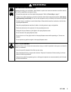
WARNING
A
fluid drain valve (J) is required in your system, to
help reduce the risk of serious injury including
splashing in the eyes or on the skin if the pump
cycles unexpectedly
.
Locate one valve downstream from the pump outlet
and another valve downstream from the surge tank
(G). These drain valves are used to relieve fluid
pressure in the pump and surge tank during shut
-
down.
1.
The surge tank (G) reduces fluid surging to pre
-
vent backflow into the pump. Mounting instructions
are supplied with the tank.
2.
The shutoff valves (D) before and after the surge
tank, and between each mix tank and the pump
fluid inlet, isolate these components for servicing.
3.
Be sure the supply line (C) between the pump and
mix tanks is level.