


4
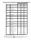
PRODUCT DESIGN
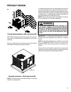
GPH13 (M Series) Package Units are designed for outdoor
installations only in either residential or light commercial ap-
plications and are available in 2, 2.5, 3, 3.5, 4 & 5 ton sizes.
They are designed for 208/230 volt single phase applications.
The connecting ductwork (Supply and Return) can be con-
nected for either horizontal or vertical airflow. In the vertical
application, a matching Roof Curb is recommended and a
horizontal duct cover kit is required.
A return air filter must be installed behind the return air grille(s)
or provision must be made for a filter in an accessible loca-
tion within the return air duct. The minimum filter area should
not be less than those sizes listed in the Specification Sec-
tion. Under no circumstances should the unit be operated
without return air filters.
A 3/4" pipe is provided for removal of condensate water from
the indoor coil. A trap must be provided to have proper con-
densate drainage. (Do not reduce the drain line size).
Refrigerant flow control is achieved by use of restrictor ori-
fices.
All heat pump models also have a suction line accumulator
installed between the reversing valve and the compressor.
The object of the accumulator is to:
1. Provide a liquid refrigerant storage vessel during prolonged
system off cycles.
2. Store excess liquid refrigerant not needed by the system
while running.
3. Return oil and saturated vapor to the compressor at a
controlled rate.
4. Retain stored excess refrigerant during a sudden system
pressure fluctuation such as seen in defrost cycles.
Refrigerant flow control is achieved by use of restrictor
orifices. These models use the FasTest Access Fitting
System, with a saddle that is either soldered to the suction
and liquid lines or is fastened with a locking nut to the access
fitting box (core) and then screwed into the saddle.
Do not
remove the core from the saddle until the refrigerant
charge has been removed. Failure to do so could result
in property damage or personal injury.
The single phase units use permanent split capacitor (PSC)
design compressors. Starting components are not required
for these units. A low microfarad run capacitor assists the
compressor to start and remains in the circuit during opera-
tion.
The outdoor fan motors are single phase capacitor type mo-
tors. Some models use PSC type indoor blower motors while
others use EEM type blower motors. EEM motors are ener-
gized by a 24V signal from the thermostat and are constant
torque motors with very low power consumption.
The EEM features an integral control module.
Air for condensing (cooling cycle) or evaporation (heating
cycle) is drawn through the outdoor coil by a propeller fan,
and is discharged vertically out the top of the unit. The out-
door coil is designed for .0 static. No additional restriction
(ductwork) shall be applied.
Conditioned air is drawn through the filter(s), field installed,
across the coil and back into the conditioned space by the
indoor blower.
Package Heat Pump indoor sections are designed to accept
optional components such as auxiliary electric heaters and
circuit breakers. Provisions for these components have been
made at time of manufacture.
GPH13 series package units use the Compliant Scroll com-
pressor; there are a number of design characteristics which
are different from the traditional reciprocating compressor.
- Due to their design Scroll compressors are inherently more
tolerant of liquid refrigerant. NOTE: Even though the com-
pressor section of a Scroll compressor is more tolerant of
liquid refrigerant, continued flood back or flooded start condi-
tions may wash oil from the bearing surfaces causing prema-
ture bearing failure.
- These Scroll compressors use "POE" or polyolester oil which
is NOT compatible with mineral oil based lubricants like 3GS.
"POE" oil must be used if additional oil is required.
- Compliant scroll compressors perform “quiet” shutdowns
that allow the compressor to restart immediately without the
need for a time delay. This compressor will restart even if the
system has not equalized.
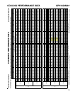
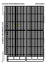
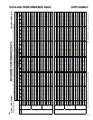
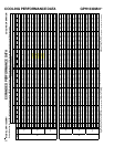
- Operating pressures and amp draws may differ from stan-
dard reciprocating compressors. This information may be
found in the “Cooling Performance Data” section.
Location and Clearances
NOTE: To ensure proper condensate drainage, unit must be
installed in a level position.