


8
IMPORTANT: Hard start components are required when
single-phase reciprocating compressors are used with
indoor coils which have thermal expansion valves. Some
units have hard start components factory installed. See
the “Specification Sheet” for hard start component require-
ments.
System Startup
PRELIMINARY CHARGE ADJUSTMENT
CAUTION
If this unit has a crankcase heater (see
Specification Sheet or wiring diagram) con-
nect electrical power to the unit for four
hours before operating the compressor.
Failure to do so could result in compressor
damage.
IMPORTANT!
During all installation and service work,
follow all regulations of the Environmental
Protection Agency (EPA). This system uses
refrigerant R-22. R-22 is an HCFC
(HydroChloro-FluoroCarbon). It is a
violation of EPA regulations to discharge
HCFC into the atmosphere and doing so
may result in fines or other penalties.
After completing system piping, leak testing, and electrical
connections, use an Allen wrench to carefully open the
suction and liquid valves on the unit. These valves do not
back seat.
WARNING
To avoid personal injury or death, open
each valve only until it touches the retainer.
To avoid loss of refrigerant, do not apply
pressure to the retainer.
The outdoor unit is factory-charged with enough R-22 for
the matching indoor blower coil or matching A-coil plus 25
feet of 3/8” liquid line. For liquid line lengths greater than 25
feet, add 0.55 oz. of R-22 per additional foot up to 50 feet.
For line sets over 50 feet consult an Amana distributor. For
liquid line lengths less than 25 feet, subtract 0.55 oz. of R-
22 per deviating foot.
CAUTION
Using refrigerant that does not meet ARI
Standard 700 may cause compressor dam-
age and void the warranty.
IMPORTANT: If adding refrigerant to a system, add only
refrigerant vapor (not liquid) through the suction valve (low
side) on the outdoor unit. Any other practice may cause
compressor damage.
FINAL CHARGE ADJUSTMENT
Matching System
This final charge adjustment procedure is for the matched
combination listed on the specification sheet.
If the outdoor temperature is 60°F or higher, set the room
thermostat to COOL, fan switch to AUTO, and set the
temperature control well below room temperature.
If the outdoor temperature is below 60°F and you are
installing a matching system, set the room thermostat to
HEAT, fan switch to AUTO, and set the temperature
control well above room temperature.
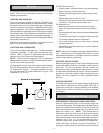
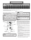
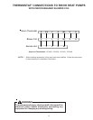
Measure the low side pressure and temperature from the
pressure tap provided. See Figure 4. Measure the high
side pressure and temperature from the liquid line service
valve.
LIQUID LINE
SERVICE VALVE
VAPOR LINE
SERVICE VALVE
LOW SIDE
GAUGE PORT
Figure 4
Turn the electrical power on, and let the system run for
several minutes. It will take some time for the refrigerant
pressures to stabilize.
Compare the operating pressures and outdoor unit amp
draw to the numbers listed in the outdoor unit “Specifica-
tion Sheet”. If pressures and amp draw are too low, add
charge. If pressures and amp draw are too high, remove
charge.
If you are not using the “Matched Combination” which is
listed on the unit "Specification Sheet", check subcooling
(TEV coils) or superheat (flowrator coils) as detailed be-
low.
AMANA-Approved Mix-Matched System Combinations
Use Amana expanded performance multiplier tables in
addition to the following procedures.