


5
5
6. Close the valve on the nitrogen cylinder and discon-
nect it from the gauge manifold.
7. Check for leaks. Apply a soap solution on all connec-
tions and joints. If you see bubbles, you have a leak.
Mark these locations.
NOTE: If you use an electronic leak detector to test for
leaks, add a trace of R-22 to the system (if permitted by
current EPA regulations) before testing.
8. Using the gauge manifold, carefully release the nitro-
gen from the system. If leaks are found, repair them.
After repair, repeat the above pressure test. If no leaks
exist, proceed to ID Coil and Line Sets Evacuation.
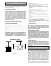
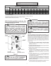
ID COIL AND LINE SETS EVACUATION
A. LOW SIDE VALVE
B. HIGH SIDE VALVE
C. VACUUM PUMP
D. THERMOCOUPLE GAUGE
E. MANIFOLD GAUGE
F. CHARGING CYLINDER
C
A
B
E
D
HIGH VACUUM PUMP
LARGE DIAMETER
BRAIDED VACUUM
HOSES
TO
RELATED
GAUGE
PORTS OF
COND. UNIT
HIGH VACUUM
MANIFOLD
LOW SIDE
GAUGE
HIGH SIDE
GAUGE
DIAL-A-CHARGE
CHARGING CYLINDER
THERMOCOUPLE
VACUUM
GAUGE
F
Figure 2
Step 1. Confirm Proper Pump And Gauge Operation
a. Connect vacuum pump, high vacuum manifold set
with high vacuum hoses, vacuum gauge and charging
cylinder to unit service valves as shown in Figure 2.
Ensure all manifold valves are fully closed.
b. Open the shutoff valve leading to the vacuum pump
(Figure 2) (C), start the pump, and watch the gauge
manifold. The readings in the gauge manifold should
drop to approximately 29 inches Hg. If this does not
happen, there is probably a leak in the pump and
gauge system. Repair the leak and test again.
c. Open the vacuum gauge valve (D) and evacuate to
250 microns or less. If the system cannot be evacu-
ated, replace the vacuum pump equipment and repeat
steps (a) through (c) again. Otherwise, the pump and
gauge are operating properly and you can continue on
to the next step; evacuating the system. Before
proceeding, be sure to close the valve (D) to the
vacuum gauge to avoid “pegging the meter” and
potential gauge damage.
WARNING
To avoid possible explosion, use only
returnable (not disposable) service
cylinders when removing refrigerant from
a system.
• Ensure the cylinder is free of damage
which could lead to a leak or explosion.
• Ensure the hydrostatic test date does not
exceed 5 years.
• Ensure the pressure rating meets or
exceeds 400 psig.
When in doubt, do not use cylinder.
LEAK TESTING
WARNING
To avoid the risk of fire or explosion, never
use oxygen, high pressure air or flammable
gases for leak testing of a refrigeration
system.
1. Before testing, ensure both hand valves on the gauge
manifold are closed relative to the center port (i.e.,
turned IN all the way.)
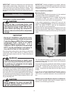
2. Attach the gauge manifold to the service valves on the
unit (see Figure 4).
Do not open the unit service valves.
Do not use refrigerant from the unit for leak testing.
The refrigerant in your unit has been precisely mea-
sured at the factory for optimum performance.
3. Connect a cylinder of dry nitrogen to the center port on
the gauge manifold.
WARNING
To avoid possible explosion, the line from
the nitrogen cylinder must include a
pressure regulator and a pressure relief
valve. The pressure relief valve must be
set to open at no more than 150 psig.
4. Open the hand valve a minimal amount on the line
coming from the nitrogen cylinder.
5. Open the high pressure valve on the manifold gauge.
Pressurize the refrigerant lines and the indoor coil to
150 psig (1034 kPA). To reach 150 psig, you may
need to further open the hand valve on the nitrogen
cylinder.
WARNING
To avoid possible explosion or equipment
damage, do not exceed 150 psig when
pressure testing.