


7
7
Electrical Connections
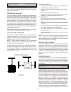
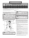
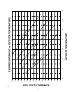
75 60 50 43 37 N/R N/R N/R N/R N/R N/R N/R N/R
118957968595347N/RN/RN/RN/RN/RN/R
18815012510795837568635854N/RN/R
301 241 201 172 150 134 120 109 100 93 86 80 75
471 376 314 269 235 209 188 171 157 145 134 125 118
N/R = NOT RECOMMENDED
Wire ampacity and voltage drop calculation based on copper conductors with 75 degree C insulation per
1996 National Electrical Code (NEC) Conductors in 86 degree F ambient.
See NEC for ampacity derating for higher ambients.
27.5 3012.5 15 17.5 20
MAXIMUM ALLOWABLE WIRE LENGTH IN FEET TO LIMIT VOLTAGE DROP TO 2%
10
MINIMUM CIRCUIT AMPACITY OF OUTDOOR UNIT (MCA)
4032.5 35 37.5
WIRE SIZE
(AWG)
22.5 25
6
14
12
10
8
Table 1
WARNING
Undersized wires can cause poor
equipment performance, equipment
damage, or fire. Consult the NEC, CEC or
a qualified electrician for proper wire size.
WARNING
To avoid personal injury, shock, or death,
be sure wiring to the unit is properly
grounded.
WIRING
Wire size is important to ensure proper unit operation. The
size must be sufficient to carry the minimum circuit ampacity
listed on the unit serial data plate. Amana recommends
sizing the wires to limit the voltage drop to a maximum of
2% from the main breaker or fuse panel to the outdoor unit.
Consult the NEC, CEC, and all local codes to determine
the correct wire gauge and necessary length of run for
proper wiring.
1. To connect unit to power supply, route the power
supply and ground wires through the high voltage
entrance in the unit.
2. Connect the ground wire to the ground lug and power
supply wires to the contactor.
3. Route the low voltage wiring through the low voltage
entrance in the unit.
4. Connect the low voltage wires to the terminal strip (if
present) or to the wire leads. Route the low voltage
wire through the wire tie provided in the unit for
restraint.
5. Connect thermostat to unit. If an Amana approved
room thermostat is not already present, install one at
a suitable indoor location.
Consult the instructions packaged with the thermostat
for mounting and location instructions. For field-sup-
plied low voltage wiring and connections, see the last
section of this manual.
6. Check all factory wiring connections to ensure none
were loosened during shipping and handling.
NOTE: This table is provided as a guide only. Wire
sizing may be regulated by local codes. Local inspection
is the final authority on wire sizing.
WARNING
To avoid personal injury, shock, or death,
open the electrical disconnect switch
before electrically connecting the unit.
Wiring must conform with National
Electrical Code (NEC) or Canadian
Electrical Code (CEC) and all local codes.
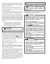
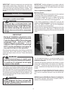
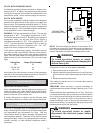
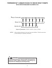
The wiring diagram for this unit can be found on the control
box cover. Refer to Figure 3 for field wiring connections.
START CAP
(if present)
START RELAY
(if present)
FIELD WIRING
HIGH VOLTAGE CONNECTION
FIELD WIRING
LOW VOLTAGE CONNECTION
GROUND LUG
W
Y
C
R
O
RUN CAP
DEFROST
BOARD
FHC
L2
L1
T1T2
CC
PS1
RV
DFS
Figure 3
WARNING
To avoid the risk of fire or equipment
damage, use only copper conductors.