


3
3
DO NOT locate the unit:
– Directly under a vent termination for a gas appliance.
– Within 3 feet of a clothes drier vent.
– Where the refreezing of defrost water would create
a hazard.
– Where water may rise into the unit.
– Where the noise would prove to be a nuisance to the
customer (i.e. windows, patios, decks, etc.)
DO locate the unit:
– With the bottom of the unit at least three inches
above the maximum expected snow accumulation
level.
– In accordance with the minimum clearances described
in Figure 1.
– To minimize the length of refrigerant piping required.
– To provide adequate service clearances.
– On a level concrete pad (or other sturdy, weather
resistant platform).
– Isolated from the building structure to avoid transmis-
sion of vibrations.
NOTE: Short runs of refrigerant piping are better than long
runs. Locate the unit to provide safe access for future
maintenance and service. If possible, discuss unit location
with the owner before proceeding.
ROOFTOP INSTALLATIONS
Before installing this unit on a roof, ensure that the roof will
support the weight of the unit, its platform, and the service
personnel. For the unit weight, see the outdoor unit
specification sheet (all weights are approximate). If there
is doubt about the adequacy of the roof, contact a qualified
architect or structural engineer before installing the unit.
Ensure the unit is placed on a level, weather-resistant
platform.
APPLICATION NOTE
For proper performance, the indoor equipment and duct-
work must be adequate for moving about 400 CFM of
indoor air for every ton of cooling capacity to be installed.
If they are not, modify the ductwork or indoor equipment
accordingly.
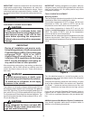
Refrigerant Piping
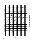
REFRIGERANT VAPOR AND LIQUID LINE SIZING
See unit “Specification Sheet” for the required vapor and
liquid line tubing sizes. The listed sizes in the specification
sheet are suitable for line lengths of fifty feet or less and
indoor coil elevations of no more than forty feet above or
below the outdoor unit. NOTE: Unit performance is
affected by vapor line tubing size. A larger than required
vapor line tubing inhibits oil return to the unit. A smaller
than required vapor line tubing size decreases unit perfor-
mance by up to 10%. If a run of more than fifty feet is
required, contact your Amana distributor for assistance.
Check the indoor coil liquid and vapor line diameter. A
bushing or coupling may be needed to match with the line
General
This manual covers only the installation of the remote heat
pump. See the unit specification sheet for information
regarding accessories.
SHIPPING AND HANDLING
Units are securely packed in shipping containers ap-
proved by the International Safe Transit Association. Check
the carton upon arrival for external damage. If damage is
found, file a request in writing for inspection by the carrier
agent immediately. The carrier is responsible for making
prompt inspection of damage and for a thorough investiga-
tion of each claim. The distributor or manufacturer will not
accept claims from dealers for transportation damage. If
no damage is found, carefully remove all shipping material
and properly dispose of it.
Keep the unit as upright as possible. Laying the unit on its
side or top could cause equipment damage.
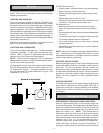
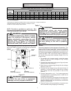
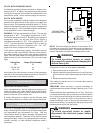
LOCATION AND CLEARANCES
This unit is for outdoor installation only. The unit cannot be
completely enclosed. At least one side must be unre-
stricted. Refer to Figure 1 for clearances from the sides
and top of the unit to walls and other objects.
NOTE: These minimum clearances do not guarantee
adequate service access. Sufficient clearances for servic-
ing the unit(s) must be provided.
If installing two or more units at the same location, allow at
least 24 inches between the units when using the 6”-12”-
12” guidelines in Figure 1. The space between two units
may be reduced to 12” if the clearances in Figure 1 are
increased to 12”-24”-24”.
12"
12"
6"
MINIMUM CLEARANCES
SIDE VIEW
5'
Figure 1