


10
ID COIL WITH EXPANSION VALVE
At stabilized cooling conditions and with an outdoor tem-
perature of 60°F or higher, the subcooling at the outdoor
unit liquid line service valve should be as specified in the
specification sheet. Add or remove charge as required.
ID COIL WITH ORIFICE
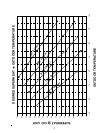
For a proper superheat reading, measure the refrigerant
pressure and temperature at the outdoor unit vapor line
service valve. The superheat should be within 3°F of that
shown on the Desired Superheat vs Outdoor Temperature
chart (see page 9). If the superheat is higher, add charge.
If the superheat is lower, remove charge.
EXAMPLE: The low side pressure is 84 psi. The low side
temperature is 80°F. The outdoor temperature is 95°F.
The indoor temperature is 85°F. By referring to a pressure
temperature chart, you will see that 84 psi equals a
saturated temperature of 50°F. The superheat is 80 - 50
= 30°F. The chart shows a superheat of 20°F is ideal for
these conditions. Since our superheat is 30 - 20 = 10°F
higher than ideal, charge must be added.
If the system is performing properly, reinstall the service
port caps and the valve bonnets. With the valve opened,
the valve bonnet is the primary seal against refrigerant
leaks. See the table below for the torque required for an
effective seal on the valve bonnet (1/6 turn past finger
tight).
Tubing Size Torque (Foot-Pounds)
3/8 10
1/2, 5/8, 3/4 14
7/8, 1 1/8 16
After closing the valve bonnet, perform a final refrigerant
leak test on the valves and sweat connections. Return the
room thermostat to the desired settings.
Troubleshooting
(QUALIFIED SERVICER ONLY)
When troubleshooting, the first step should always be to
check for clean coils, clean filter(s), and proper airflow.
Indoor airflow should be 350 to 450 CFM per ton of cooling,
based on the size of the outdoor unit.
If further information is needed, see the Remote Heat
Pump Service Manual or contact your Amana distributor.
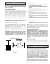
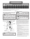
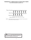
Defrost System
Your unit is equipped with a time/temperature defrost
board. Defrosting of the outdoor coil is determined by both
coil temperature and compressor run time. See the
“Specification Sheet” for factory settings. Adjustment can
be changed as required. There are 30, 60, and 90 minute
settings available. Adjust only if geographical conditions,
outdoor humidity, or other adverse conditions make it
necessary.
CRWOY
DEFROST
BOARD
30
TEST
FAN
CC
HI-P
LO-P
DFS
RV
60
90
DEFROST TIME
ADJUSTMENT PIN
Figure 5
NOTE: If the time select pin remains in test position for 5
minutes, the control will ignore test mode and assume a
normal 90 minute defrost cycle. To over ride this time out,
remove the select pin briefly and replace back on test.
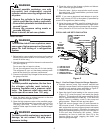
WARNING
To avoid electrical shock or death,
disconnect the power before changing the
defrost time cycle.
If adjustment of the run time appears advisable:
1. Disconnect power to outdoor unit.
2. Move the defrost time adjustment pin from 90 minutes
to 60 minutes or 30 minutes as required (refer to Figure
5).
3. Reconnect the electrical power.
The maximum defrost time is 14 minutes. Most defrost
cycles are shorter.
SERVICING: When servicing, it may be necessary to
rapidly advance the system through a defrost cycle. To do
this:
Place the defrost time adjustment pin on Test. When the
unit starts the defrost cycle, quickly remove the time select
pin to allow normal defrosting and defrost termination to
proceed. The select pin may be reconnected to test or
repeat the defrost cycle, or the pin may be placed in the
desired time setting. (Jumping both test pins with a small
insulated screw driver will also work.)
WARNING
To avoid electrical shock or death,
disconnect the electrical power before
servicing.