


46
COMFORTNET™ SYSTEM
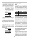
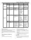
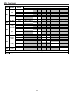
Submenu Item User Modifiable Options Comments
Cool Airflow (CL CFM) 18, 24, 30, 36, 42, 48, or 60, default
is 18
Selects the airflow for the non-CT
compatible single stage AC unit
Cool Airflow Trim (CL TRM) -10% to +10% in 2% increments,
default is 0%
Selects the airflow trim amount for the non-
CT compatible single stage AC unit
Cool Airflow Profile (CL PRFL) A, B, C, or D, default is A Selects the airflow profile for the non-CT
compatible single stage AC unit
Cool ON Delay (CL ON) 5, 10, 20, or 30 seconds, default is
5 seconds
Selects the indoor blower ON delay for the
non-CT compatible single stage AC unit
Cool OFF Delay (CL OFF) 30, 60, 90, or 120 seconds, default
is 30 seconds
Selects the indoor blower OFF delay for the
non-CT compatible single stage AC unit
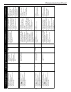
NON-COMM (APPLIES ONLY TO A CT COMPATIBLE FURNACE MATCHED
WITH A NON-CT COMPATIBLE SINGLE STAGE AIR CONDITIONER)
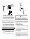
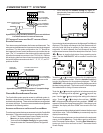
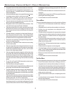
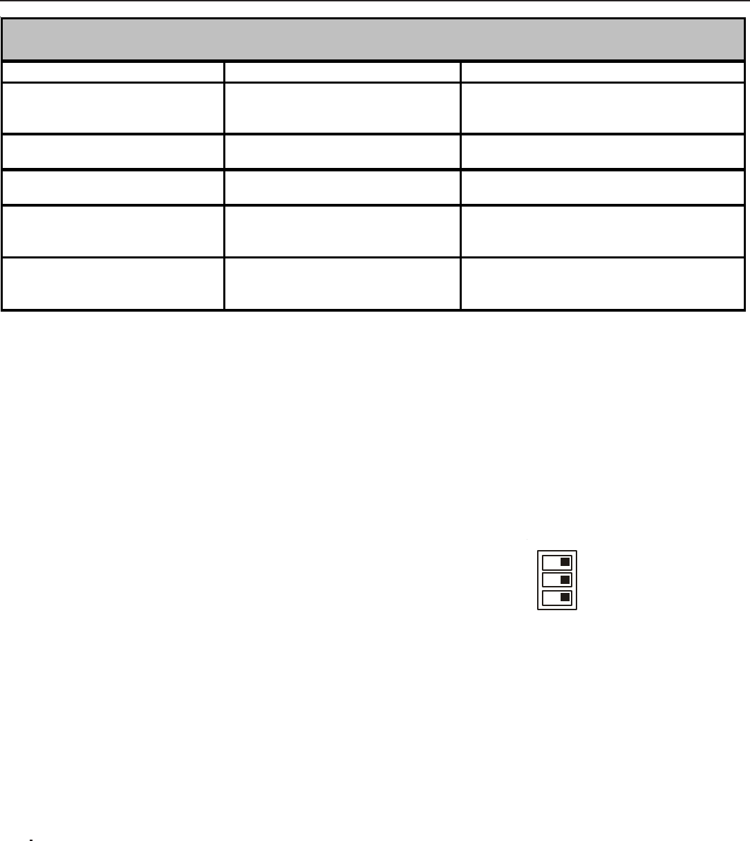
The indoor control is equipped with a bank of three dipswitches
that provide biasing and termination functions for the communi-
cations transmission lines. The outdoor control in the CT™
compatible unit is equipped with a bank of two dipswitches that
provide termination functions for the communications transmis-
sion lines. Communications errors will result if these switches
are not correctly set. The table below indicates the switch posi-
tion for the bias and termination dipswitches along with the ex-
pected voltages. Note that the ON position is the correct posi-
tion for all bias and termination dipswitches.
1
2
ONOFF
3
BIAS
BIAS
TERM
Indoor Unit BIAS and TERMINATION Dipswitches
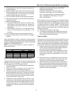
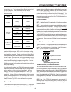
The ComfortNet system is a fully communicating system, and
thus, constitutes a network. Occasionally the need to trouble-
shoot the network may arise. The integrated furnace control has
some on-board tools that may be used to troubleshoot the net-
work. These tools are: red communications LED, green receive
(Rx) LED, and learn button.
• Red communications LED – Indicates the status of the
network. The table below indicates the LED status and
the corresponding potential problem.
• Green receive LED – Indicates network traffic. The table
below indicates the LED status and the corresponding
potential problem.
• Learn button – Used to reset the network. Depress the
button for approximately 2 seconds to reset the network.
THERMOSTAT MENU
If this furnace is installed with a CT compatible heat pump, the
system is recognized as a dual fuel system. The balance point
temperature should be set via the thermostat advanced menu.
Navigate to the THERMOSTAT menu. Press the INSTALLER
CONFIG key. Navigate to the SETUP menu and press the IN-
STALLER CONFIG button. Navigate to dF BAL PNT. Adjust
the dual fuel system balance point using the back/forward ar-
rows.
DIAGNOSTICS
Accessing the furnace’s diagnostics menu provides ready ac-
cess to the last six faults detected by the furnace. Faults are
stored most recent to least recent. Any consecutively repeated
fault is stored a maximum of three times. Example: A clogged
return air filter causes the furnace limit to trip repeatedly. The
control will only store this fault the first three consecutive times
the fault occurs. Navigate to the diagnostics menu as described
above in Accessing and Navigating the Advanced Features Menus.
NOTE: It is highly recommended that the fault history be cleared
when performing maintenance or servicing the furnace.
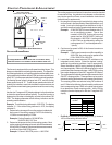
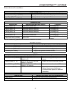
NETWORK TROUBLESHOOTING
Communications is achieved by taking the difference between
two dc signals. The signals and transmission lines are referred
to as “data 1” and “data 2”. Each transmission line is biased to
approximately 2.5Vdc. During data reception/transmission, the
data lines vary between +5V and ground. (When data 1 is in-
creasing towards +5V, data 2 is decreasing towards ground and
when data 1 is decreasing towards ground, data 2 is increasing
towards +5V. Typically, the data 1 line is approximately 2.6Vdc
and the data 2 transmission line is approximately 2.3Vdc. The
voltage difference between data 1 and data 2 is typically 0.2 to
0.6 Vdc.