


42
COMFORTNET™ SYSTEM
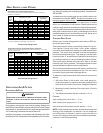
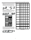
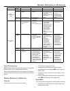
7. Select the heating speed for your model from the heating
speed chart in the Specification Sheet. The adjust setting
(already established by the cooling speed selection)
determines which set of speeds are available. The selected
speed must provide a temperature rise within the rise range
listed with the particular model.
Example: The *MVC950704CX is set for 990 CFM on
cooling, the “ADJUST” is set to “+” (plus). The
four heating speeds available are “A Plus”, “B
Plus”, “C Plus”, and “D Plus”. “A Plus” has a
rise of 46°F for both stages which is within
the 30-60°F rise range for the *MVC950704CX.
This setting will keep electrical consumption
to a minimum. Set the “Heat” speed DIP
switches to “A”.
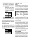
78
AOFFOFF
B* ON OFF
COFFON
DONON
Switch Bank: S4
Heating Speed
Taps
DIP Sw itch No.
(*Indicates factory setting)
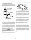
8. Select the desired “heating” speed tap by positioning
switches 7 and 8 appropriately. Refer to figure above. Verify
CFM by noting the number displayed on the dual 7-segment
LED display.
In general lower heating speeds will: reduce electrical consump-
tion, lower operating sound levels of the blower, and increase the
outlet air temperature delivered to the home. The speeds avail-
able allow the blower performance to be optimized for the particu-
lar homeowner’s needs.
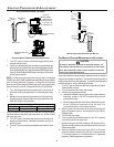
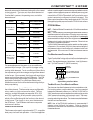
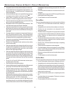
BLOWER H EAT O FF D ELAY T IMINGS
The integrated control module provides a selectable heat off delay
function. The heat off delay period may be set to 90, 120, 150, 180
seconds using the DIP switches or jumper provided on the control
module. The delay is factory shipped at 150 seconds but may be
changed to suit the installation requirements and/or homeowner
preference. Refer to the following figures for switch positions and
corresponding delay times.
12
90 seconds OFF OFF
120 seconds ON OFF
150 seconds* OFF ON
180 seconds ON ON
Heat OFF Delay
DIP Switch No.
Switch Bank: S1
(*Indicates factory setting)
Heat Off Delay Dipswitches
C
OMFORT
N
ET
™ S
YSTEM
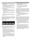
OVERVIEW
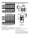
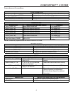
The ComfortNet system (or CT™ system) is a system that in-
cludes a ComfortNet compatible furnace and air conditioner or
heat pump with a CTK01AA thermostat. A valid ComfortNet sys-
tem could also be a compatible furnace, CTK01AA thermostat
and non-compatible, single stage air conditioner. Any other sys-
tem configurations are considered invalid ComfortNet systems and
must be connected as a traditional (or legacy) system (see Elec-
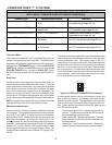
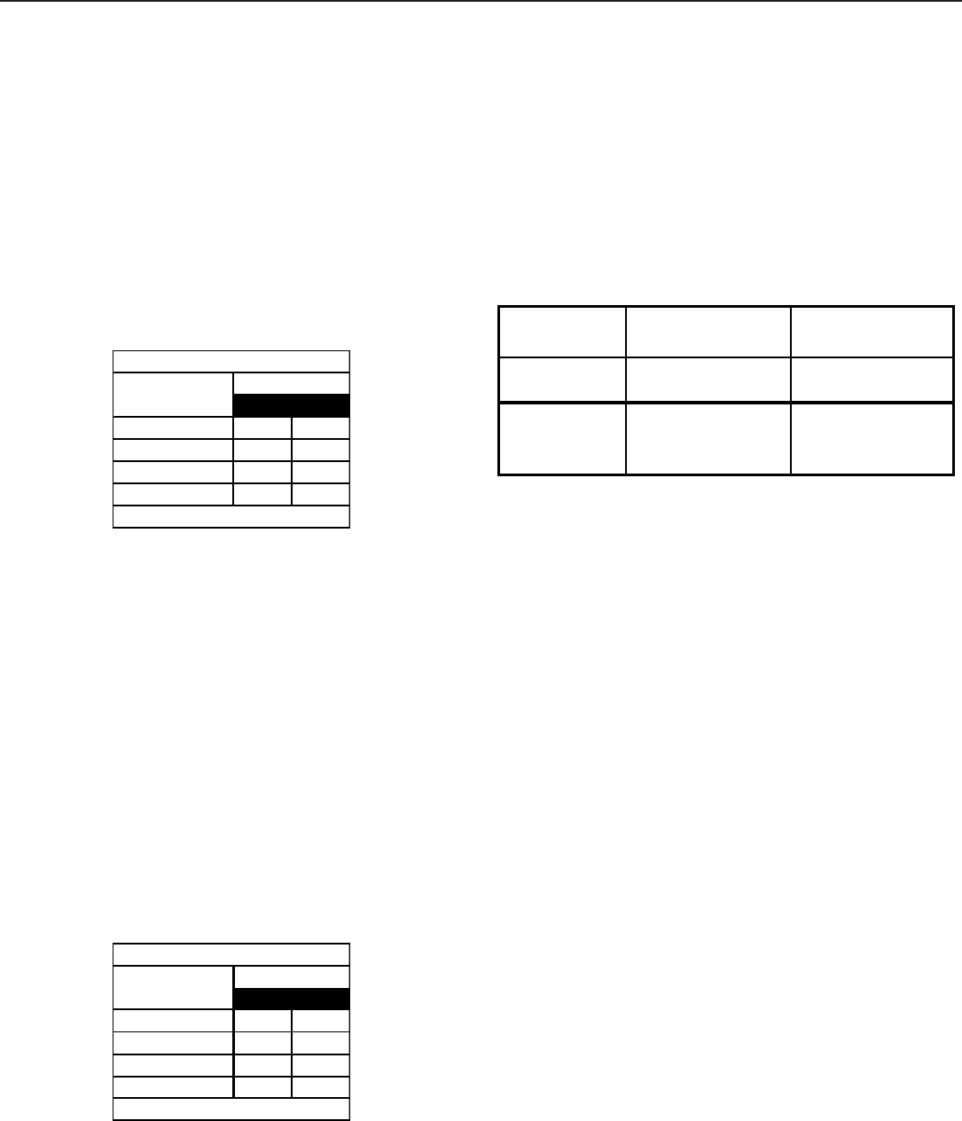
trical Connections for wiring connections). The table below com-
pares the valid CT systems.
CT compatible
Furnace
CT compatible
Air Conditioner
Full CT system
benefits and features
CT compatible
Furnace
CT compatible
Heat Pump
Full CT system
benefits and features
CT compatible
Furnace
Non-CT compatible
Single Stage
Air Conditioner
CT system
benefits and features
for furnace only
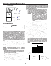
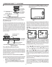
A ComfortNet heating/air conditioning system differs from a legacy/
traditional system in the manner in which the indoor unit, outdoor
unit and thermostat interact with one another. In a traditional sys-
tem, the thermostat sends commands to the indoor and outdoor
units via analog 24 VAC signals. It is a one-way communication
path in that the indoor and outdoor units typically do not return
information to the thermostat.
On the other hand, the indoor unit, outdoor unit, and thermostat
comprising a ComfortNet system “communicate” digitally with one
another. It is now a two-way communications path. The thermo-
stat still sends commands to the indoor and outdoor units. How-
ever, the thermostat may also request and receive information from
both the indoor and outdoor units. This information may be dis-
played on the CT thermostat. The indoor and outdoor units also
interact with one another. The outdoor unit may send commands
to or request information from the indoor unit. This two-way digital
communications between the thermostat and subsystems (indoor/
outdoor unit) and between subsystems is the key to unlocking the
benefits and features of the ComfortNet system.
Two-way digital communications is accomplished using only two
wires. The thermostat and subsystem controls are power with 24
VAC. Thus, a maximum of 4 wires between the equipment and
thermostat is all that is required to operate the system.
AIRFLOW CONSIDERATIONS
Airflow demands are managed differently in a fully commu-
nicating system than they are in a legacy wired system.
The system operating mode (as determined by the thermo-
stat) determines which unit calculates the system airflow
demand. If the indoor unit is responsible for determining
the airflow demand, it calculates the demand and sends it
to the ECM motor. If the outdoor unit or thermostat is
responsible for determining the demand, it calculates the