


26
C
ONDENSATE
D
RAIN
L
INES
& D
RAIN
T
RAP
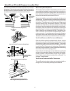
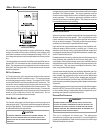
LEFT SIDE DOWN
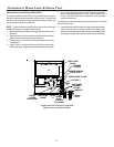
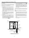
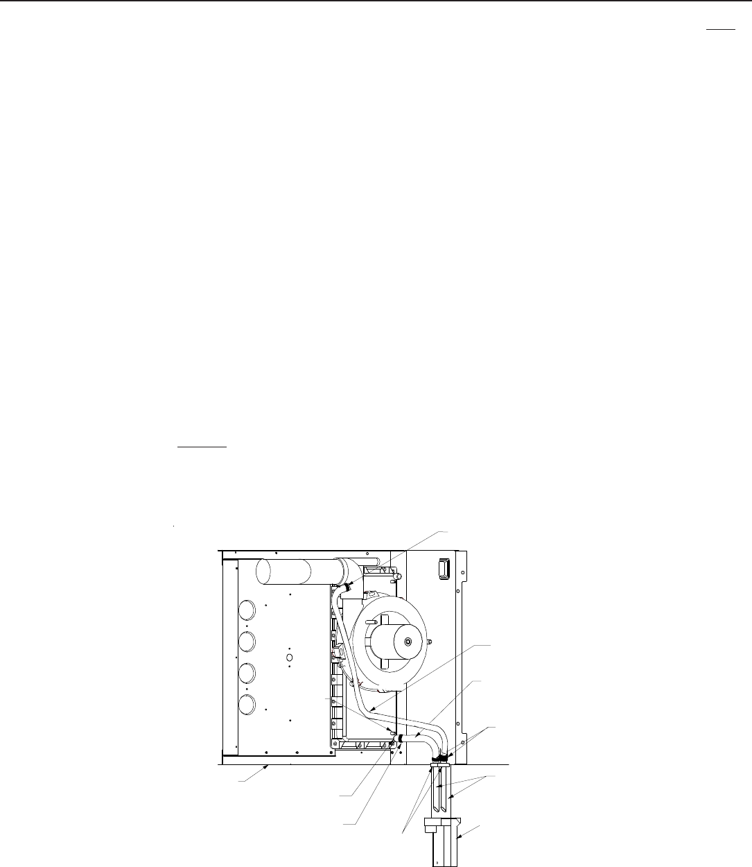
Horizontal installations with the left side panel down will require
drain hoses to be connected to the left side front cover drain port
and the side drain port on the rubber elbow.
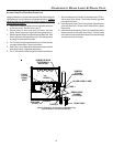
1. Remove the rubber plug/cap from the front cover left (down)
side drain port.
2. Relocate the front cover pressure switch hose connection
from the right side (as shipped) pressure tap to the left
(down) side tap. The pressure switch hose must be
connected to the down side to guard against blocked drain
conditions. Cut hose to appropriate length to minimize
sagging. Plug right (unused) pressure tap with plug
removed from left side.
3. Secure Hose A to front cover drain port with a red hose
clamp. Route hose to rear left (down) side panel grommet
holes. NOTE: For left side drainage, grommets must be
relocated to left side panel.
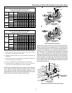
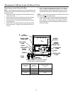
4. Remove the rubber cap from the side drain port on the
rubber elbow.
5. Secure the short end of Hose B to rubber elbow side drain
port using a green hose clamp. NOTE: For left side
drainage, route hose to far left (down) side panel grommet
holes. NOTE: Horizontal left side connections (when using
new side port drain elbow) does not require connecting a
hose to the induced draft blower housing.
6. Cut 5 1/2 inches straight length from the long end of each
Tube 2 and discard radius ends.
7. Insert approximately one inch of each Tube 2 through left
side panel grommet hole. Secure tubes to Hose A and
Hose B with a green hose clamps. NOTE: Tube must
reach bottom of trap. Ensure hoses and tubes maintain a
downward slope for proper drainage and that they are not
kinked or binding.
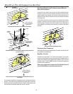
For details concerning mounting of the drain trap, refer to Con-
densate Drain Lines and Drain Trap - Horizontal Drain Trap Mount-
ing.
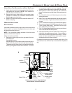
HORIZONTAL DRAIN TRAP MOUNTING (LEFT OR RIGHT SIDE
PANEL)
1. Position the drain trap against side panel with drain tubes
inserted into trap. Note that the trap may be orientated
with the outlet facing either the furnace’s top cover or base
pan.
2. Secure drain trap to side panel at the dimples or crosshairs
located on either side of the grommet drain holes.
3. Confirm that tubes reach bottom of drain trap and that all
hoses maintain a downward slope and are not kinked or
binding.
4. Attach PVC drain line to drain trap outlet with either a 90°
elbow or coupling.
LEFT SIDE
PANEL
FRONT COVER
DRAIN PORT
SIDE PANEL
GROMMET
HOLES
DRAIN TRAP
TUBE(S) 2
GREEN HOSE
CLAMP
HOSE A
HOSE B
FRONT
COVER
PRESSURE
TAP
RED HOSE CLAMP
GREEN HOSE
CLAMP
Horizontal Connections - Left Side Down
(Upflow Shown, Counterflow Similar)