


28
E
LECTRICAL
C
ONNECTIONS
1. Measure resistance between the neutral (white) connection
and one of the burners.
2. Resistance should measure 10 ohms or less.
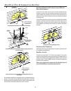
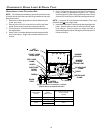
This furnace is equipped with a blower door interlock switch which
interrupts unit voltage when the blower door is opened for servicing.
Do not defeat this switch.
24 VOLT T HERMOSTAT W IRING
W
IRE
ROUTING
MUST
NOT
INTERFERE
WITH
CIRCULATOR
BLOWER
OPERATION
,
FILTER
REMOVAL
OR
ROUTINE
MAINTENANCE
.
A
REMOVABLE
PLUG
CONNECTOR
IS
PROVIDED
WITH
THE
CONTROL
TO
MAKE
THERMOSTAT
WIRE
CONNECTIONS
.T
HIS
PLUG
MAY
BE
REMOVED
,
WIRE
CONNECTIONS
MADE
TO
THE
PLUG
,
AND
REPLACED
.I
T
IS
RECOMMENDED
THAT
MULTIPLE
WIRES
INTO
A
SINGLE
TERMINAL
BE
TWISTED
TOGETHER
PRIOR
TO
INSERTING
INTO
THE
PLUG
CONNECTOR
.F
AILURE
TO
DO
SO
MAY
RESULT
IN
INTERMITTENT
OPERATION
.
STRONGLY
IMPORTANT NOTE
As a two-stage non-communicating furnace, the furnace integrated
control module provides terminals for both “W1” and “W2”, and
“Y1” and “Y2” thermostat connections. This allows the furnace to
support the following system applications: ‘Two-Stage Heating
Only’, ‘Two-Stage Heating with Single Stage Cooling’, and ‘Two-
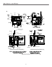
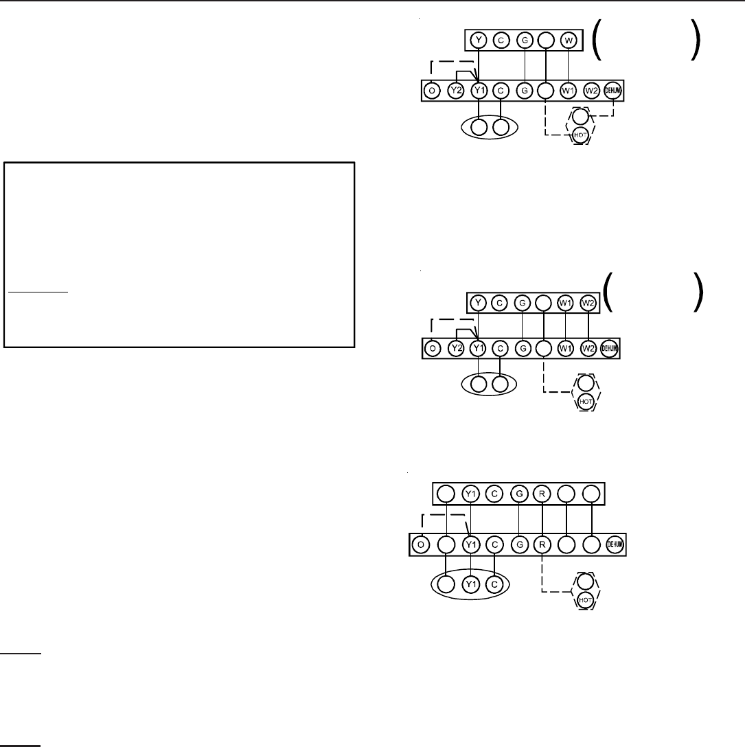
Stage Heating with Two-Stage Cooling’. Refer to the following fig-
ures for proper connections to the integrated control module.
Low voltage connections can be made through either the right or
left side panel. Thermostat wiring entrance holes are located in the
blower compartment. The following figure shows connections for a
“heat/cool system”.
This furnace is equipped with a 40 VA transformer to facilitate use
with most cooling equipment. Consult the wiring diagram, located
on the blower compartment door, for further details of 115 Volt and
24 Volt wiring.
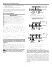
NOTE: For single stage cooling applications, a jumper must be
located between Y1 and Y2 at the furnace control in order to
achieve the desired single stage cooling airflow. Use of ramping
profiles and dehumidification features require a jumper between
Y1 and O and Y1 and DEHUM, respectively.
NOTE: Thermostat “R” required if outdoor unit is equipped with a
Comfort Alert™ module or if the out door unit is a part of the
ComfortNet family of equipment AND is wired as a legacy
system.
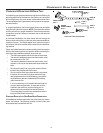
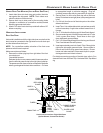
R
Y C
NEU
Furnace Integrated
Control Module
Remote
Condensing Unit
(Single-Stage Cooling)
Dehumidistat
[Optional]
To apply a single-stage Heating Thermostat,
the thermostat selector switch on the
Integrated Control Module be set on
single-stage.
must
NOTE:
Single Stage Heating with Single Stage Cooling
Thermostat
Single Stage Heating with
Single Stage Cooling
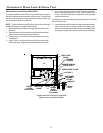
R
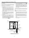
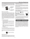
Two-Stage Heating with Single-Stage Cooling
R
Y C
Furnace Integrated
Control Module
Thermostat
Two-Stage Heating
with
Single-Stage Cooling
Remote
Condensing Unit
(Single-Stage Cooling)
Dehumidistat
[Optional]
NEU
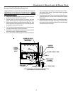
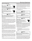
R
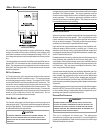
Two-Stage Heating with Two-Stage Cooling
W1 W2
Y2
Furnace Integrated
Control Module
Thermostat
Two-Stage Heating
with
Two-Stage Cooling
(
)
Remote
Condensing Unit
(Two-Stage Cooling)
Dehumidistat
[Optional]
Y2
NEU
W1 W2
Y2
Thermostat Wiring Diagrams
SINGLE-STAGE H EATING T HERMOSTAT A PPLICATION
A single-stage thermostat with only one heating stage may be
used to control this furnace. The application of a single-stage
thermostat offers a timed transition from low to high fire. The
furnace will run on low stage for a fixed period of time before step-
ping up to high stage to satisfy the thermostat’s call for heat. The
delay period prior to stepping up can be set at either a fixed 5
minute time delay or a load based variable time between 1 and 12
minutes (AUTO mode). If the AUTO mode is selected, the control
averages the cycle times of the previous three cycles and uses
the average to determine the time to transition from low stage to
high stage.