


7
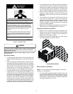
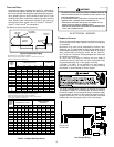
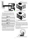
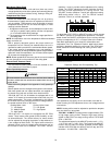
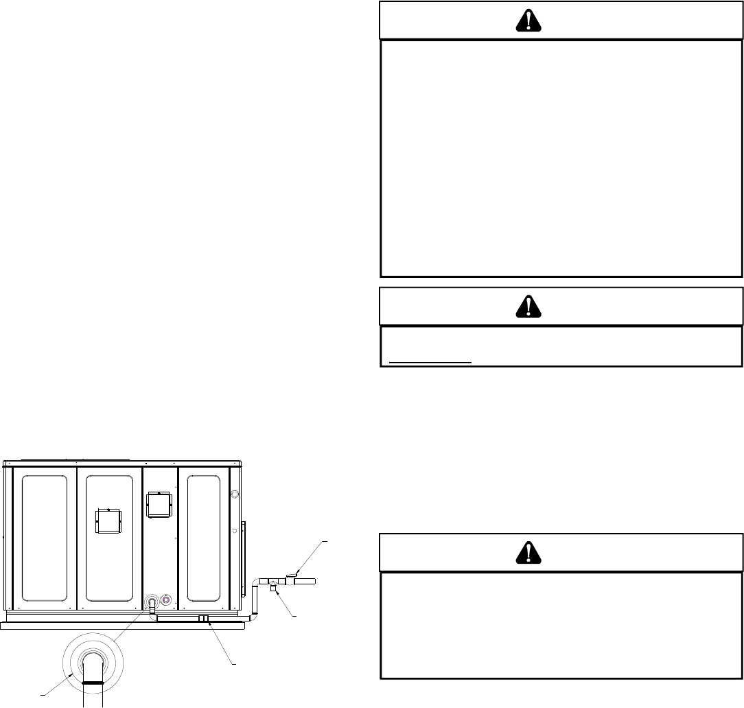
Refer to the Proper Piping Practice drawing for the general layout
at the unit. The following rules apply:
1. Use black iron pipe and fittings for the supply piping. The
use of a flex connector and/or copper piping is permitted
as long as it is in agreement with local codes.
2. Use pipe joint compound on male threads only. Pipe joint
compound must be resistant to the action of the fuel used.
3. Use ground joint unions.
4. Install a drip leg to trap dirt and moisture before it can enter
the gas valve. The drip leg must be a minimum of three
inches long.
5. Use two pipe wrenches when making connection to the gas
valve to keep it from turning.
6. Install a manual shut-off valve in a convenient location
(within six feet of unit) between the meter and the unit.
7. Tighten all joints securely.
8. The unit must be connected to the building piping by one
of the following methods:
• Rigid metallic pipe and fittings
• Semirigid metallic tubing and metallic fittings (Aluminum
alloy tubing must not be used in exterior locations)
• Listed gas appliance connectors used in accordance with
the terms of their listing that are completely in the same
room as the equipment
• In the prior two methods above the connector or tubing
must be protected from physical and thermal damage.
Aluminum alloy tubing and connectors must be coated to
protect against external corrosion when in contact with
masonry, plaster or insulation or are subject to repeated
wettings by liquids (water - not rain water, detergents or
sewage)
DRIP LEG
MANUAL
SHUT-OFF
VALVE
GROUND JOINT UNION
(INSTALLED AHEAD OF GAS VALVE)
GROMMET
Proper Piping Practice
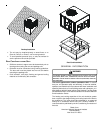
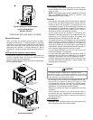
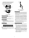
NOTE: The unit gas supply entrance is factory sealed with plugs.
Keep plugs in place until gas supply is ready to be installed. Once
ready, replace the plugs with the supplied grommets and install gas
supply line.
GAS PIPING CHECKS
CAUTION
T
O PREVENT PROPERTY DAMAGE OR PERSONAL INJURY DUE TO FIRE, THE
FOLLOWING INSTRUCTIONS MUST BE PERFORMED REGARDING GAS
CONNECTIONS AND PRESSURE TESTING:
•
T
HE UNIT AND ITS GAS CONNECTIONS MUST BE LEAK TESTED BEFORE
PLACING IN OPERATION.
B
ECAUSE OF THE DANGER OF EXPLOSION OR
FIRE, NEVER USE A MATCH OR OPEN FLAME TO TEST FOR LEAKS.
N
EVER
EXCEED SPECIFIED PRESSURES FOR TESTING.
H
IGHER PRESSURE MAY
DAMAGE GAS VALVE AND CAUSE OVERFIRING WHICH MAY RESULT IN
PREMATURE HEAT EXCHANGE FAILURE.
•
T
HIS UNIT AND ITS SHUT-OFF VALVE MUST BE DISCONNECTED FROM
THE GAS SUPPLY DURING ANY PRESSURE TESTING OF THAT SYSTEM AT
TEST PRESSURES IN EXCESS OF 1/2
PSIG
(3.48 K
P
A).
•
T
HIS UNIT MUST BE ISOLATED FROM THE GAS SUPPLY SYSTEM BY
CLOSING ITS MANUAL SHUT-OFF VALVE DURING ANY PRESSURE
TESTING OF THE GAS SUPPLY PIPING SYSTEM AT TEST PRESSURES
EQUAL TO OR LESS THAN 1/2
PSIG
(3.48 K
P
A).
WARNING
T
O AVOID PROPERTY DAMAGE OR PERSONAL INJURY
, BE SURE THERE IS
NO OPEN FLAME IN THE VICINITY DURING AIR BLEEDING.
There will be air in the gas supply line after testing for leaks
on a new installation. Therefore, the air must be bled from the
line by loosening the ground joint union until pure gas is
expelled. Tighten union and wait for five minutes until all gas
has been dissipated in the air. Be certain there is no open
flame in the vicinity during air bleeding procedure. The unit is
placed in operation by closing the main electrical disconnect
switch for the unit.
PROPANE GAS INSTALLATIONS
WARNING
T
O AVOID PROPERTY DAMAGE, PERSONAL INJURY OR DEATH DUE TO FIRE
OR EXPLOSION CAUSED BY A PROPANE GAS LEAK, INSTALL A GAS
DETECTING WARNING DEVICE.
S
INCE RUST CAN REDUCE THE LEVEL
OF ODORANT IN PROPANE GAS, A GAS DETECTING WARNING DEVICE
IS THE ONLY RELIABLE WAY TO DETECT A PROPANE GAS LEAK.
C
ONTACT A LOCAL PROPANE GAS SUPPLIER ABOUT INSTALLING A
GAS DETECTING WARNING DEVICE.
IMPORTANT NOTE: Propane gas conversion kits must be
installed to convert units to propane gas.
All propane gas equipment must conform to the safety
standards of the National Board of Fire Underwriters (See NBFU
Manual 58).
For satisfactory operation, propane gas supply pressure must
be within 9.7 - 10.3 inches W.C. at the manifold with all gas
appliances in operation. Maintaining proper gas pressure
depends on three main factors:
1. Vaporization rate, which depends on (a) temperature of the
liquid, and (b) wetted surface area of the container or
containers.
2. Proper pressure regulation.
3. Pressure drop in lines between regulators, and between
second stage regulator and the appliance. Pipe size
required will depend on length of pipe run and total load of
all appliances.