


6
TRANSPORTATION D AMAGE
Check the carton upon arrival for external damage. If damage is
found, a request for inspection by carrier agent should be made in
writing immediately.
Carefully inspect the unit for damage including damage to the
cabinetry. Any bolts or screws which may have loosened in transit
must be re-tightened. In the event of damage, the receiver should:
1. Make notation on delivery receipt of any visible damage to
shipment or container.
2. Notify carrier promptly and request an inspection.
3. In case of concealed damage, carrier should be notified
as soon as possible-preferably within 5 days.
4. File the claim with the following supporting documents:
a. Original Bill of Lading, certified copy, or indemnity bond.
b. Original paid freight bill or indemnity in lieu thereof.
c. Original invoice or certified copy thereof, showing trade
and other discounts or reductions.
d. Copy of the inspection report issued by carrier
representative at the time damage is reported to the
carrier. The carrier is responsible for making prompt
inspection of damage and for a thorough investigation of
each claim. The distributor or manufacturer will not accept
claims from dealers for transportation damage.
NOTE: When inspecting the unit for transportation damage, remove
all packaging materials. Recycle or dispose of the packaging ma-
terial according to local codes.
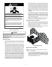
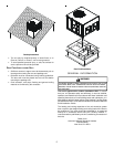
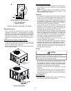
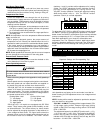
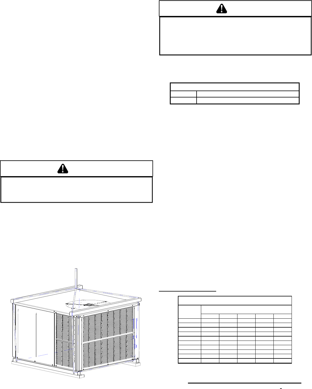
RIGGING DETAILS
WARNING
T
O PREVENT PROPERTY DAMAGE, THE UNIT SHOULD REMAIN IN AN UPRIGHT
POSITION DURING ALL RIGGING AND MOVING OPERATIONS.
T
O FACILITATE
LIFTING AND MOVING WHEN A CRANE IS USED, PLACE THE UNIT IN AN
ADEQUATE CABLE SLING.
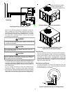
Important: If using bottom discharge with roof curb, ductwork should
be attached to the curb prior to installing the unit. Ductwork dimen-
sions are shown in roof curb installation instructions.
Refer to the Roof Curb Installation Instructions for proper curb in-
stallation. Curbing must be installed in compliance with the National
Roofing Contractors Association Manual.
Lower unit carefully onto roof mounting curb. While rigging unit,
center of gravity will cause condenser end to be lower than supply
air end.
Rigging
GAS PIPING
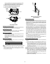
IMPORTANT NOTE: This unit is factory set to operate on natural
gas at the altitudes shown on the rating plate.
WARNING
T
O AVOID PROPERTY DAMAGE, PERSONAL INJURY OR DEATH WHEN EITHER
USING PROPANE GAS ALONE OR AT HIGHER ALTITUDES, OBTAIN AND INSTALL
THE PROPER CONVERSION KIT(S).
F
AILURE TO DO SO CAN RESULT IN
UNSATISFACTORY OPERATION AND/OR EQUIPMENT DAMAGE.
H
IGH ALTITUDE
KITS ARE FOR
U
.
S
. INSTALLATIONS ONLY AND ARE NOT APPROVED FOR USE
IN
C
ANADA.
The rating plate is stamped with the model number, type of gas and
gas input rating. Make sure the unit is equipped to operate on the
type of gas available. Conversion to LP gas is permitted with the
use of the factory authorized conversion kit LPT-00A.
Inlet Gas Pressure
Natural Min. 5.0" W.C., Max. 10.0" W.C.
Propane Min. 11.0" W.C., Max. 13.0" W.C.
Inlet Gas Pressure Must Not Exceed the Maximum Value Shown in Table
Above.
The minimum supply pressure should not vary from that shown in
the table above because this could prevent the unit from having
dependable ignition. In addition, gas input to the burners must not
exceed the rated input shown on the rating plate. Overfiring of the
unit could result in premature heat exchanger failure.
HIGH ALTITUDE DERATE (U.S. INSTALLATIONS ONLY)
IMPORTANT NOTE: The gas/electric units naturally derate with al-
titude. Do not attempt to increase the firing rate by changing ori-
fices or increasing the manifold pressure. This can cause poor com-
bustion and equipment failure. At all altitudes, the manifold pres-
sure must be within 0.3 inches W.C. of that listed on the nameplate
for the fuel used. At all altitudes and with either fuel, the air tempera-
ture rise must be within the range listed on the unit nameplate.
Refer to the Installation Manual provided with the LP kit for conver-
sion from natural gas to propane gas and for altitude adjustments.
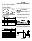
PIPING
IMPORTANT NOTE: To avoid possible unsatisfactory operation or
equipment damage due to under firing of equipment, do not under-
size the natural/propane gas piping from the meter/tank to the unit.
When sizing a trunk line, include all appliances on that line that
could be operated simultaneously.
The rating plate is stamped with the model number, type of gas
and gas input rating. Make sure the unit is equipped to operate on
the type of gas available. The gas line installation must comply
with local codes, or in the absence of local codes, with the latest
edition of the National Fuel Gas Code NFPA 54/ANSI Z223.1.
Natural Gas Connection
Len
g
th of
Pipe in Feet
1/2 3/4
1
1 1/4 1 1/2
10 132 278 520 1050 1600
20 92 190 350 730 1100
30 73 152 285 590 980
40 63 130 245 500 760
50 56 115 215 440 670
60 50 105 195 400 610
70 46 96 180 370 560
80 43 90 170 350 530
90 40 84 160 320 490
100 38 79 150 305 460
Pressure = .50 PSIG or less and Pressure Drop of 0.3" W.C. (Based
on 0.60 S
p
ecific Gravit
y
Gas
)
Natural Gas Capacity of Pipe
in Cubic Feet of Gas Per Hour (CFH)
Nominal Black Pipe Size (inches)
BTUH Furnace Input
Heatin
g
Value of Gas
(
BTU/Cubic Foot
)
CFH =