


18
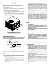
MAIN BURNER FLAME (QUALIFIED SERVICER ONLY)
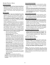
Flames should be stable, soft and blue (dust may cause
orange tips but must not be yellow). The flames must extend
directly outward from the burner without curling, floating or
lifting off.
Check the burner flames for:
1. Good adjustment
2. Stable, soft and blue
3. Not curling, floating, or lifting off.
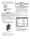
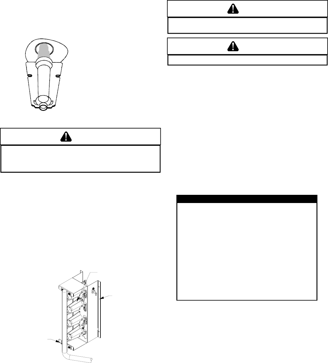
Burner Flame
WARNING
T
O AVOID PERSONAL INJURY OR DEATH DUE TO ELECTRIC SHOCK,
DO NOT REMOVE ANY INTERNAL COMPARTMENT COVERS OR ATTEMPT ANY
ADJUSTMENT.
C
ONTACT A QUALIFIED SERVICER AT ONCE IF AN ABNORMAL
FLAME SHOULD DEVELOP.
At least once a year, prior to or during the heating season,
make a visual check of the burner flames.
NOTE: This will involve removing and reinstalling the heat exchanger
door on the unit, which is held by two screws. If you are uncertain
about your ability to do this, contact a qualified servicer.
If a strong wind is blowing, it may alter the airflow pattern within the
unit enough that an inspection of the burner flames is not pos-
sible.
CLEANING B URNERS
1. Shut off electric power and gas supply to the unit.
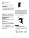
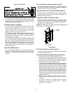
2. Remove the screws securing the manifold to the burner
retention bracket. Remove the manifold and rotate each
burner counterclockwise to remove.
Burner
Bracket
Burner
Manifold
Manifold Assembly
3. Remove the burners.
4. Use a bottle brush to clean burner insert and inside of the
burners.
5. Replace burners and manifold, inspect the burner
assembly for proper seating of burners in retention slots.
6. Reconnect electrical power and gas supply.
CAUTION
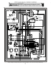
L
ABEL ALL WIRES PRIOR TO DISCONNECTION WHEN SERVICING CONTROLS.
W
IRING ERRORS CAN CAUSE IMPROPER AND DANGEROUS OPERATION.
CAUTION
A
LWAYS VERIFY PROPER OPERATION AFTER SERVICING.
For further information on the yearly inspection, consult the
User Manual. It is recommended that a qualified servicer inspect
and service the unit at least once each year.
Turn the unit on at the thermostat. Wait a few minutes, since
any dislodged dust will alter the normal flame appearance.
Flames should be predominantly blue and directed into the
tubes. They should not be yellow. They should extend directly
outward from the burner ports without curling downward,
floating or lifting off the ports.
ACCESSORIES AND FUNCTIONAL PARTS
SHEET M ETAL A CCESSORIES
Additional accessories can be purchased to fit specific application
needs. Parts and instructions are available from your distributor.
FUNCTIONAL P ARTS
Auxliary Limit Switch Flame Roll-out Switch
Blower Housing Flame Sensor
Circulator Blower Motor Gas Orifice
Blower Wheel Gas Valve
Burner Heat Exchanger
Capacitor High Limit Switch
Compressor Igniter
Condenser Coil Ignition Control
Condenser Fan Blade Induced Draft Blower
Condenser Fan Motor Pressure Switch
Contactor Pressure Switch Hose
Gas Manifold Transformer
Evaporator Coil
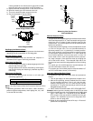
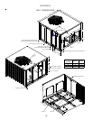
FUNCTIONAL PARTS
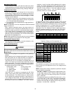
Functional Parts List
GENERAL I NFORMATION
1. Refer to the description in Functional Parts List when
ordering any of the listed functional parts. Be sure to provide
the unit model and serial numbers with the order.
2. Although only functional parts are shown, all sheet metal
parts, doors, etc. may be ordered by description.
3. Parts are available from your distributor.