


13
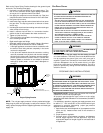
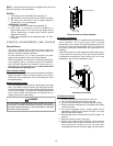
Gas Line
Gas
Shutoff
Valve
Gas Line
To Furnace
Drip Leg Cap
With Fitting
Manometer Hose
Manometer
Open To
Atmosphere
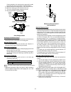
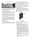
Measuring Inlet Gas Pressure
Alternate Method
Manifold Pressure Check
The gas valve has a tapped opening to facilitate measurement
of the manifold pressure. A “U” Tube manometer having a scale
range from 0 to 12 inches of water should be used for this
measurement. The manifold pressure must be measured with
the burners operating.
To adjust the pressure regulator, remove the adjustment screw
or cover on the gas valve. Turn out (counterclockwise) to
decrease pressure, turn in (clockwise) to increase pressure.
Only small variations in gas flow should be made by means
of the pressure regulator adjustment. In no case should the
final manifold pressure vary more than plus or minus 0.3
inches water column from the specified nominal pressure.
Any major changes in flow should be made by changing the
size of the burner orifices. The measured input rate to the
furnace must not exceed the rating specified on the unit rating
plate.
For natural gas, the manifold pressure must be between 3.2
and 3.8 inches water column (3.5 nominal).
For propane gas, the manifold pressure must be between 9.7
and 10.3 inches water column (10.0 nominal).
Gas Input (Natural Gas Only) Check
To measure the gas input use a gas meter and proceed as
follows:
1. Turn off gas supply to all other appliances except the unit.
2. With the unit operating, time the smallest dial on the meter
for one complete revolution. If this is a 2 cubic foot dial,
divide the seconds by 2; if it is a 1 cubic foot dial, use the
seconds as is. This gives the seconds per cubic foot of gas
being delivered to the unit.
3. INPUT=GAS HTG VALUE x 3600 / SEC. PER CUBIC FOOT
Example: Natural gas with a heating value of 1000 BTU per cubic
foot and 34 seconds per cubic foot as determined by Step 2, then:
Input = 1000 x 3600 / 34 = 106,000 BTU per Hour. NOTE:
BTU content of the gas should be obtained from the gas
supplier. This measured input must not be greater than
shown on the unit rating plate.
4. Relight all other appliances turned off in step 1. Be sure all
pilot burners are operating.
If having waited for five minutes and no gas smell is noted,
move the gas control valve switch to the ON position.
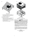
9. Replace the heat exchanger door on the side of the unit.
10. Open the manual gas valve external to the unit.
11. Turn on the electrical power supply to the unit.
12. Set the thermostat to desired setting.
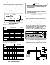
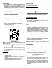
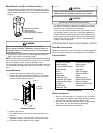
OUTLET
INLET
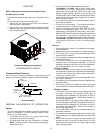
Gas Valve
On/Off
Selector
Switch
White-Rodgers Model 36F22
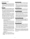
Gas Valve
On/Off
Selector
Switch
INLET
OUTLE
T
White-Rodgers 36G22
Gas Supply And Manifold Check
Gas supply pressure and manifold pressure with the burners
operating must be as specified on the rating plate.
Gas Inlet Pressure Check
Gas inlet pressure must be checked and adjusted in
accordance to the type of fuel being consumed.
With Power And Gas Off:
1. Connect a water manometer or adequate gauge to the inlet
pressure tap of the gas valve.
Inlet gas pressure can also be measured by removing the
cap from the dripleg and installing a predrilled cap with a
hose fitting.
With Power And Gas On:
2. Put unit into heating cycle and turn on all other gas
consuming appliances.
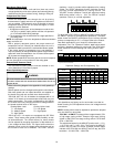
Natural Min. 5.0" W.C., Max. 10.0" W.C.
Propane Min. 11.0" W.C., Max. 13.0" W.C.
Inlet Gas Pressure
NOTE: Inlet Gas Pressure Must Not Exceed the Maximum Value
Shown.
If operating pressures differ from above, make necessary
pressure regulator adjustments, check piping size, etc., and/
or consult with local utility.