


15
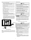
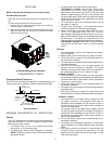
Dehumidification
The GE ECM motor has the capability to provide increased
dehumidification during cooling operation. This is
accomplished by lowering the airflow to approximately 85%
of the nominal cooling airflow. Example: Unit is operating at
1400 CFM and humidistat calls for dehumidification. Resulting
airflow is 0.85* 1400 CFM = 1190 CFM.
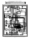
To make use of this feature, a 24VAC humidistat which
opens on humidity rise is required. Connect humidistat to
the HUMIDISTAT/HUM terminal on the low voltage terminal
board (see wiring diagram in the appendix). Clip the HUM/
PJ6 jumper on the low voltage terminal board. The system
is now ready to provide dehumidification.
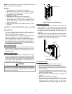
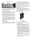
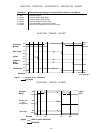
Limit Check
Check limit control operation after 15 minutes of operation
by blocking the return air grille(s).
1. After several minutes the main burners must go OFF.
Blower will continue to run.
2. Remove air restrictions and main burners will relight
after a cool down period of a few minutes.
Adjust the thermostat setting below room temperature.
1. Main burners must go OFF.
2. Circulating Air Blower will continue to run for 120, 135 or
150 seconds, depending on the setting.
*PG13(48,60)***1A ONLY: Circulating Air Blower will
continue to run for 180 seconds.
1
2
3
10
11
12
9
6
23
6
5
8
9
11
12
L2
L2L2
L2
D1
L1
L1 UNUSED
HEAT
COOL
FS
K2
K1
R8
R10
R3
K4
K3
R31
LED
1
0
6
8
-
8
3
-
4
0
0
A
C27
D3
R38
D9
D10
R34
R35
R4
R11
R42
D12
R36
D11
D14
C20
Z
1
R29
R22
C13
R25
D5
D7
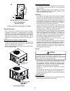
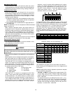
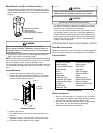
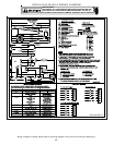
Control Board (Top)
NOTE: If necessary, adjust fan OFF delay settings to obtain satis-
factory comfort level.
WARNING
THIS UNIT MUST NOT BE USED AS A "CONSTRUCTION HEATER" DURING THE
FINISHING PHASES OF CONSTRUCTION ON A NEW STRUCTURE.
T
HIS TYPE OF
USE MAY RESULT IN PREMATURE FAILURE OF THE UNIT DUE TO EXTREMELY
LOW RETURN AIR TERMPERATURES AND EXPOSURE TO CORROSIVE OR VERY
DIRTY ATMOSPHERES.
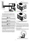
Unit Shutdown
1. Set the thermostat to lowest setting.
2. Turn off the electrical power supply to the unit.
3. Remove the heat exchanger door on the side of the unit by
removing screws.
4. Move the gas control valve switch to the OFF position. Do
not force.
5. Close manual gas shutoff valve external to the unit.
6. Replace the heat exchanger door on the unit.
7. If cooling and/or air circulation will be desired, turn ON the
electrical power.
COOLING S TARTUP
NOTE: Check all manual reset limit controls in heating circuit if
cooling mode does not operate.
Compressor Protection Devices
The compressor includes components which are designed
to protect the compressor against abnormal operating
conditions.
WARNING
T
O PREVENT PERSONAL INJURY OR DEATH, ALWAYS DISCONNECT ELECTRICAL
POWER BEFORE INSPECTING OR SERVICING THE UNIT.
ALL COMPRESSOR
PROTECTION DEVICES RESET AUTOMATICALLY, ENERGIZING THE CONTACTOR
AND OUTDOOR FAN.
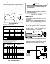
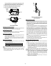
Cooling Refrigerant Charging
Check unit charge before putting the cooling section into full
operation. The unit is factory charged with R-22 for nominal air
flow and static pressure conditions. The unit has a piston
flowrator expansion device.
NOTE: *PG1360 is equipped with a thermostatic valve expansion
device.
To ensure the unit is properly charged for the intended
application, check the unit refrigerant superheat at the
compressor. The refrigerant superheat is a function of outdoor
ambient temperature and return air temperature of the
conditioned space. It is the installing contractors responsibility
to ensure the proper refrigerant superheat at the compressor
is adjusted for each application. For example, 10 degree
refrigerant superheat level is adequate for a 95 degree outdoor
ambient temperature and a 78 - 80 degree for indoor return air
temperature. As the outdoor ambient temperature rises the
superheat decreases and as the outdoor ambient temperature
lowers the superheat increases. Proper superheat adjustment
optimizes cooling performance.
For models equipped with thermostatic expansion valve, charge
system to 12-14 degrees of subcooling, adjust expansion valve
stem for superheat setting when necessary.
NOTE: The expansion valve will not need adjustment for most
applications. Ensure system superheat is set between 10-12 degrees
after final adjustment.
Cooling Operation
NOTE: Mechanical cooling cannot be reliably provided at ambient
temperatures below 50° F.
1. Turn on the electrical power supply to the unit.
2. Place the room thermostat selector switch in the COOL
position (or AUTO if available, and if automatic changeover
from cooling to heating is desired).
3. Set the room thermostat to the desired temperature.
TROUBLESHOOTING
IGNITION CONTROL ERROR CODES
The following presents probable causes of questionable unit
operation. Refer to Diagnostic Indicator Chart for an
interpretation of the signal and to this section for an explanation.
Remove the control box access panel and note the number of
diagnostic LED flashes. Refer to Diagnostic Indicator Chart
for an interpretation of the signal and to this section for an
explanation.