


6
Local codes often require a disconnect switch located near the
unit; do not install the switch on the unit. Refer to the installa-
tion instructions supplied with the indoor furnace/air handler for
specific wiring connections and indoor unit configuration. Like-
wise, consult the instructions packaged with the thermostat
for mounting and location information.
Overcurrent Protection
The following overcurrent protection devices are approved for
use.
• Time delay fuses
• HACR type circuit breakers
These devices have sufficient time delay to permit the motor-
compressor to start and accelerate its load.
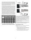
Three Phase Compressor Rotation
Use care when handling scroll compressors. Dome temp-
eratures could be hot.
CAUTION
Three phase compressors are power phase dependent and can
rotate in either direction.
Verify proper rotation for three phase compressors by ensuring
the suction pressure drops and discharge pressure rises when
the compressor is energized. NOTE: When operated in re-
verse, a three phase scroll compressors is noisier and its cur-
rent draw substantially reduced compared to marked values.
To correct, disconnect power and switch any two leads at the
unit contactor and re-observe.
High Voltage Connections
Route power supply and ground wires through the high voltage
port and terminate in accordance with the wiring diagram pro-
vided inside the control panel cover.
Low Voltage Connections
Condensing unit control wiring requires 24 Volt minimum, 25VA
service from the indoor transformer. Route control wires through
the low voltage port and terminate in accordance with the wir-
ing diagram provided inside the control panel cover.
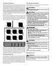
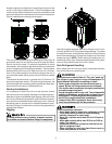
Single-Stage Thermostat
with Two Low Voltage Wires to Remote
System Start Up
POSSIBLE REFRIGERANT LEAK
To avoid a possible refrigerant leak, open the service
valves until the top of the stem is 1/8” from the retainer.
CAUTION
When opening valves with retainers, open each valve only until
the top of the stem is 1/8” from the retainer. To avoid loss of
refrigerant, DO NOT apply pressure to the retainer. When open-
ing valves without a retainer remove service valve cap and in-
sert a hex wrench into the valve stem and back out the stem
by turning the hex wrench counterclockwise. Open the valve
until it contacts the rolled lip of the valve body.
NOTE: These are not back-seating valves. It is not necessary
to force the stem tightly against the rolled lip.
The service valve cap is the secondary seal for the valves and
must be properly tightened to prevent leaks. Make sure cap is
clean and apply refrigerant oil to threads and sealing surface
on inside of cap. Tighten cap finger-tight and then tighten addi-
tional 1/6 of a turn (1 wrench flat), or to the following specifica-
tion, to properly seat the sealing surfaces.
1. 3/8” valve to 5 - 10 in-lbs
2. 5/8” valve to 5 - 20 in-lbs
3. 3/4” valve to 5 - 20 in-lbs
4. 7/8” valve to 5 - 20 in-lbs
Do not introduce liquid refrigerant from the cylinder into the
crankcase of the compressor as this may damage the
compressor.
POSSIBLE REFRIGERANT LEAK
To avoid a possible refrigerant leak, open the service
valves until the top of the stem is 1/8” from the retainer.
CAUTION
NOTICE
REFRIGERANT MUST BE ADDED TO THE SYSTEM AFTER
EVACUATION IS COMPLETE.
REFRIGERANT UNDER PRESSURE!
• Do not overcharge system with refrigerant.
• Do not operate unit in a vacuum or at negative pres-
sure.
Failure to follow proper procedures may cause
property damage, personal injury or death.
WARNING
1. Add refrigerant amount for the unit being installed. See
unit rating plate for initial charge.
2. Set thermostat to call for cooling. Check indoor and out-
door fan operation and allow system to stabilize for 10
minutes for fixed orifices and 20 minutes for expansion
valves.