


8
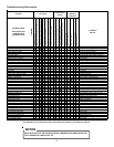
TROUBLESHOOTING ANALYSIS TABLE
COMPLAINT PROBABLE CAUSE REMEDY
1. Excessive charge of refrigerant in system. 1. Purge or pump-down excessive charge.
2. Inadequate supply of air across the 2. Make certain that coil is not fouled in any
condenser coil. way, or that air is not re-circulating.
3. Non-condensate gases in the system. 3. Purge these gases from the system.
Recharge system, if necessary.
1. System low on refrigerant. 1. Charge system until sight glass is clear of bubbles.
2. Compressor valves broken. 2. Replace compressor.
1. Liquid line valve closed. 1. Open the liquid line valve.
2. Restricted liquid line. 2. Replace filter-dryer.
3. The bulb of the thermal expansion valve 3. Detach the bulb from the suction line and hold
has lost its charge. in one hand. If no liquid refrigerant goes through
the valve, replace the valve.
4. System low on refrigerant. 4. Test the unit for leaks. Add refrigerant until sight
glass is free from bubbles, after repairing leak.
5. Dirty filters. 5. Clean or replace filter.
6. Coil frosted up. 6. Defrost and clean coil. Clean or replace filters.
7. Flash gas in the liquid line. 7. Excessive liquid line drop. Check liquid line size.
8. Quantity of air through evaporator not adequate. 8. Increase the blower speed.
1. Expansion valve stuck open. 1. Correct valve action or replace the valve.
2. Expansion valve bulb not in contact with 2. Fasten bulb securely to suction line.
suction line.
3. Suction and/or discharge valve leaking or broken. 3. Replace compressor.
1. Disconnect switch open. 1. Close the disconnect switch.
2. Blow fuse or fuse at disconnect switch. 2. Check the cause of failure and replace the fuse.
3. Thermostat set too high. 3. Adjust to lower temperature.
4. Selector switch in "Off" position. 4. Turn selector switch knob to "Cool" position.
5. Contactor and/or relay coils burned out. 5. Replace contactor and/or relay.
6. Loose or open electrical connection in either 6. Inspect and secure all electrical connections.
the control or power circuit.
5. Compressor will not start.
1. High Head Pressure
2. Low Head Pressure
3. Low Suction Pressure
4. High Suction Pressure
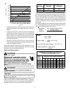
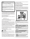
Wiring Diagram
HIGH VOLTAGE!
D
ISCONNECT
ALL
POWER
BEFORE
SERVICING
OR
INSTALLING
THIS
UNIT
.
M
ULTIPLE
POWER
SOURCES
MAY
BE
PRESENT
. F
AILURE
TO
DO
SO
MAY
CAUSE
PROPERTY
DAMAGE
,
PERSONAL
INJURY
OR
DEATH
.