


6
Example:
A
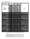
7 ½ Ton unit is to be installed. The distance from the
building to the unit is 75’. Calculate the minimum wire size
assuming no more than 2% voltage drop.
MCA for 7 Ton 230V unit = 43.3 (from S&R plate).
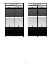
Applying previous table wire sizes less than #8 AWG
cannot be used for circuits which have a rating of 45A.
The #8 wire is not suitable since the maximum length for
a 45A circuit is 68’.
Solution: Use a #6 AWG wire suitable up to 110’.
NOTE: It is the contractors’s responsibility to follow the
NEC (USA) or CEC (Canada) when sizing the service
wire for this unit.
½
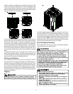
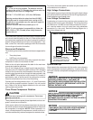
Local codes often require a disconnect switch located near the
unit; do not install the switch on the unit. Refer to the installa-
tion instructions supplied with the indoor furnace/air handler for
specific wiring connections and indoor unit configuration. Like-
wise, consult the instructions packaged with the thermostat
for mounting and location information.
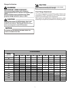
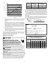
Overcurrent Protection
The following overcurrent protection devices are approved for
use.
• Time delay fuses
• HACR type circuit breakers
These devices have sufficient time delay to permit the motor-
compressor to start and accelerate its load.
Refer to the unit serial plate and this table for the maximum
overcurrent protection permitted.
Run all line voltage wiring a conduit from the service discon-
nect box to the unit. Refer to the NEC (USA) or CEC (Canada)
codes for the correct size conduit based on the wire size. The
conduit enters the control box through the hole provided in the
bottom. NOTE: The control box hole is sized for 3/4” conduit. If
permitted by code, a flexible conduit is preferred to minimize
vibration transmission from the unit to the building.
Connect the line voltage wires to the L1, L2, and L3 terminals
of the definite purpose contactor (located in the unit control
box). Refer to the wiring diagram attached to the unit when
making these connections.
Three Phase Compressor Rotation
Use care when handling scroll compressors. Dome temp-
eratures could be hot.
CAUTION
Three phase scrolls are power phase dependent and can com-
press in more than one direction.
Verify proper rotation for three phase compressors by ensuring
the suction pressure drops and discharge pressure rises when
the compressor is energized. NOTE: When operated in re-
verse, a three phase scroll compressors is noisier and its cur-
rent draw substantially reduced compared to marked values.
To correct, disconnect power and switch any two leads at the
unit contactor and re-observe.
High Voltage Connections
Route power supply and ground wires through the high voltage
port and terminate in accordance with the wiring diagram pro-
vided inside the control panel cover.
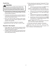
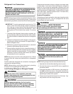
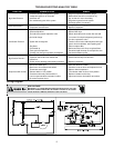
Low Voltage Connections
Condensing unit control wiring requires a two-conductor low
voltage circuit from the room thermostat. The wiring should be
no smaller than 18 AWG and the field connection for this cir-
cuit must be made in the unit control box using solderless
connectors (i.e. wire nuts). See the following diagram for a
typical low voltage hook-up.
SINGLE STATE LOW VOLTAGE HOOK-UP
YELLOW
BLACK
WHITE
BLUE BLUE
THERMOSTAT CHT18-60
CONDENSING
UNIT
CKL090/120
Y1
W1
RG
AIR
HANDLER
AH090/120
RED
NOTES:
1). THERMOSTAT TO AIR HANDLER CABLE
MUST HAVE A MINIMUM OF (4) CONDUCTORS
2). AIR HANDLER TO CONDENSING UNIT CABLE
MUST HAVE A MINIMUM OF (2) CONDUCTORS
WIRE NUT
GREEN
System Start Up
Never operate the compressor with the suction valve closed to
test the compressor’s pumping efficiency. In some cases, this
can result in serious compressor damage and loss of warranty
coverage.
NOTICE
THIS UNIT IS SHIPPED WITH A NITROGEN/HELIUM
HOLDING CHARGE ONLY. UNIT MUST BE
EVACUATED AND CHARGED PER INSTALLATION
INSTRUCTIONS WITH REFRIGERANT LISTED ON
SERIAL RATING PLATE.
UNITS SHIPPED WITH A HOLDING CHARGE ARE
INTENDED FOR COMPONENT REPLACEMENT
ONLY ON EXISTING SYSTEMS, AND NOT
INTENDED FOR USE IN NEW SYSTEMS OR NEWLY
CONSTRUCTED HOMES.
NOTICE
NOTICE
UNITS MUST ONLY BE USED AS REPLACEMENT
COMPONENTS FOR PRE-2010 INSTALLED
SYSTEMS.