


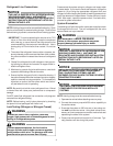
5
5000
4500
4000
3500
3000
2500
2000
1500
1000
500
0 1 2 3 4 5 6 7 8 9
10
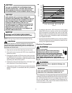
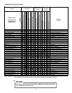
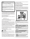
LEAK(S)
PRESENT
MINUTES
V
ACUUM
IN
MICRONS
CONDENSIBLES OR SMALL
LEAK PRESENT
NO LEAKS
NO CONDENSIBLES
• If the pressure rises to 1000 microns or less and remains
steady the system is considered leak-free; proceed to
startup.
• If pressure rises above 1000 microns but holds steady
below 2000 microns, moisture and/or noncondensibles
may be present or the system may have a small leak.
Return to step 2: If the same result is encountered check
for leaks as previously indicated and repair as necessary
then repeat evacuation.
• If pressure rises above 2000 microns, a leak is present.
Check for leaks as previously indicated and repair as nec-
essary then repeat evacuation.
Refer to the Remote Condensing Unit Service Manual for more
detailed instructions on system evacuation, preliminary charge
adjustment, and final charge adjustment.
Electrical Connections
HIGH VOLTAGE!
Disconnect ALL power before servicing.
Multiple power sources may be present.
Failure to do so may cause property damage,
personal injury or death due to electric shock.
Wiring must conform with NEC or CEC and all
local codes. Undersized wires could cause
poor equipment performance, equipment damage
or fire.
WARNING
To avoid the risk of fire or equipment damage, use
copper conductors.
WARNING
NOTICE
Units with reciprocating compressors and non-bleed TXV’s
require a Hard Start Kit.
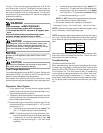
This unit is designed for three phase operation. DO NOT OP-
ERATE ON A SINGLE PHASE POWER SUPPLY. Measure
the power supply to the unit. The supply voltage must be in
agreement with the unit rating plate power requirements.
RATED
VOLTAGE
MINIMUM SUPPLY
VOLTAGE
MAXIMUM SUPPLY
VOLTAGE
208/230V 197 253
460V 414 506
The condensing unit rating plate lists pertinent electrical data
necessary for proper electrical service and overcurrent protec-
tion. Wires should be sized to limit voltage drop to 2% (max.)
from the main breaker or fuse panel to the condensing unit.
Consult the NEC, CEC, and all local codes to determine the
correct wire gauge and length. The wire size must be sufficient
to carry the Minimum Circuit Ampacity (MCA) listed on the
serial plate.
The supply voltage can be unbalanced (phase to phase) within
2%. The following formula can be used to determine the per-
centage of voltage unbalance for your unit.
Percentage
Voltage
Unbalance
=
Max. Voltage Deviation Form
Average Voltage
Average Voltage
Example:
L1-L2 = 220V
L2-L3 = 216V
Average Voltage = (220 + 216 + 213)/3
=649/3
Maximum Deviation from Average = 220 - 216 = 4
% Voltage Unbalance = 100 x (4/216)
= 400/216
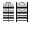
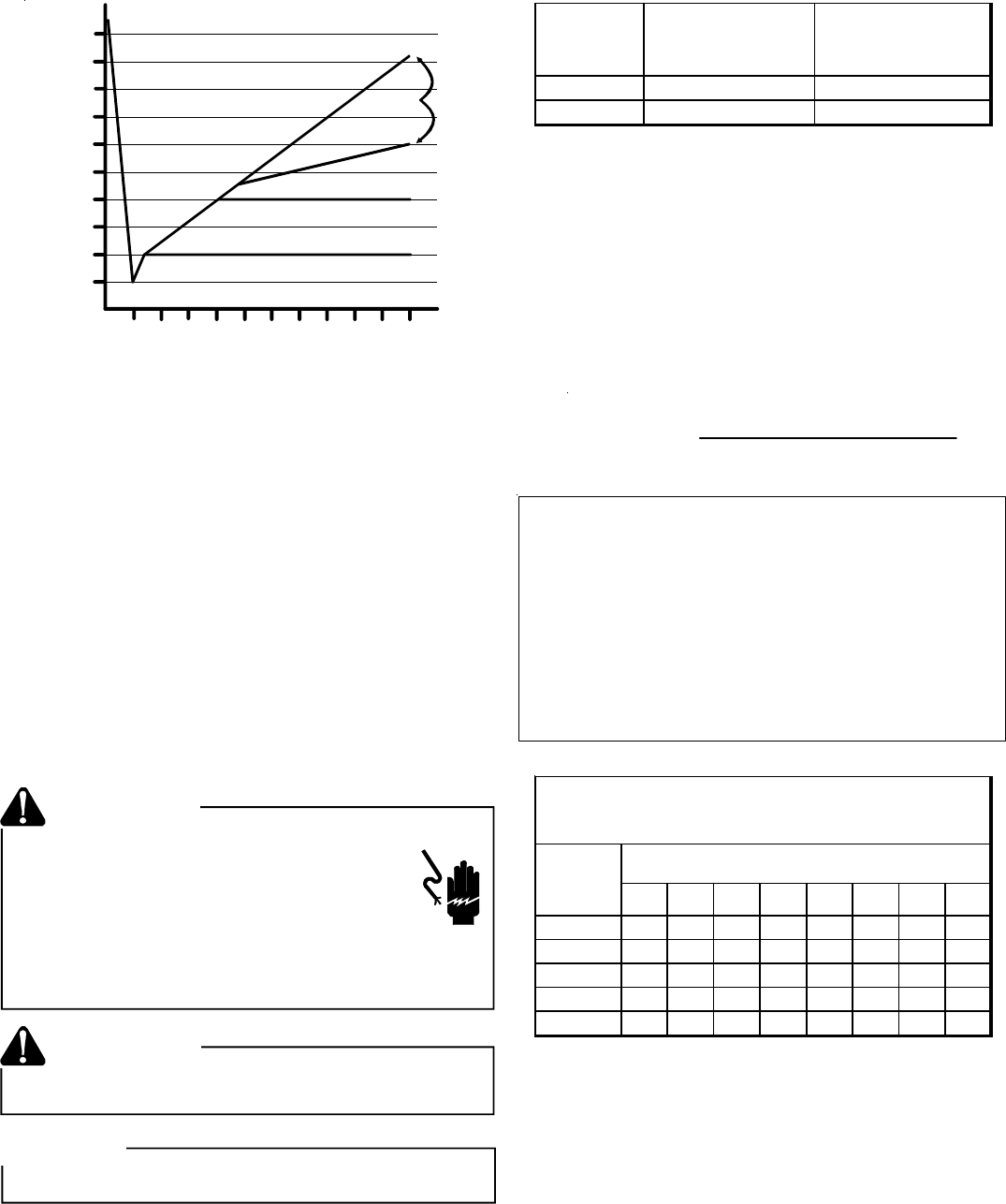
10 15 20 25 30 35 40 45
14 75 50 37 NR NR NR NR NR
12 118 79 59 47 NR NR NR NR
10 188 125 95 75 63 54 NR NR
8 301 201 150 120 100 86 75 68
6 471 314 235 188 157 134 118 110
*Based on NEC 1996
MAXIMUM ALLOWABLE LENGTH IN FEET
TO LIMIT VOLTAGE DROP TO 2%
Minimum Circuit Ampacity (MCA)
Wire
Size
(AWG)