


7
For the 7-1/2 ton unit starting charge should be 15 lb of R-22
and 18 lbs for the 10 ton unit. The length of line set, indoor unit
airflow, condensing unit location and number of tubing fittings
will have an impact on final unit charge amount. Turn the elec-
trical power on, and let the system run. Wait for the refrigerant
pressures to stabilize.
Charge Verification
REFRIGERANT UNDER PRESSURE!
• Do not overcharge system with refrigerant.
• Do not operate unit in a vacuum or at negative pres-
sure.
Failure to follow proper procedures may cause
property damage, personal injury or death.
WARNING
Use refrigerant certified to AHRI standards. Use of used
refrigerant may cause compressor damage that is not
covered under warranty. Most portable machines cannot
clean used refrigerant to meet AHRI standards.
CAUTION
NOTICE
Violation of EPA regulations may result in fines or other
penalties.
Operating the compressor with the suction valve closed
may cause serious compressor damage.
CAUTION
Final Charge Adjustment
The outdoor temperature must be 60°F or higher. Set the room
thermostat to COOL, fan switch to AUTO, and set the tem-
perature control well below room temperature.
After system has stabilized per startup instructions, check
subcooling and superheat as detailed in the following section.
Expansion Valve System
1. Purge gauge lines. Connect service gauge manifold
tobase-valve service ports. Run system at least 10 min-
utes to allow pressure to stabilize.
2. Temporarily install thermometer on liquid (small) line near
liquid line service valve with adequate contact and insu-
late for best possible reading.
3. Check subcooling and superheat. Systems with TXV ap-
plication should have a subcooling of 11 ± 2 ºF and su-
perheat of 9 ± 1 ºF.
a. If subcooling and superheat are low, adjust TXV
to 9 ± 1 ºF superheat, then check subcooling.
NOTE: To adjust superheat, turn the valve stem clock-
wise to increase and counter clockwise to decrease.
b. If subcooling is low and superheat is high, add
charge to raise subcooling to 11 ± 2ºF then check
superheat.
c. If subcooling and superheat are high, adjust TXV
valve to 9 ± 1 ºF superheat, then check subcooling.
d. If subcooling is high and superheat is low, adjust
TXV valve to 9 ± 1 ºF superheat and remove charge
to lower the subcooling to 11 ± 2ºF.
NOTE: Do NOT adjust the charge based on suction pres-
sure unless there is a gross undercharge.
4. Disconnect manifold set, installation is complete.
Subcooling Formula = Sat. Liquid Temp. - Liquid Line Temp.
NOTE: Check the Schrader ports for leaks and tighten valve
cores if necessary. Install caps finger-tight.
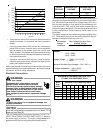
NOTE: Subsequent opening and replace of the cap will require
only 1/2 to 1 hex flat. See the table below for the torque required
for an effective seal on the valve bonnet (1/6 turn past finger
tight.
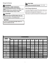
TUBING SIZE
TORQUE
(ft-lbs)
5/8 14
1 3/8 16
After closing the valve bonnet, perform a final refrigerant leak
test on the valves and sweat connections. Return the room
thermostat to the desired settings.
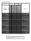
Troubleshooting
Qualified Installer/Servicer Only
When troubleshooting, the first step should always be to check
for clean coils, clean filter(s), and proper airflow. Indoor airflow
should be 375 to 425 CFM per ton of cooling based on the size
of the outdoor unit. The most common way of establishing
indoor airflow is heating temperature rise. Indoor airflow will
then be (Heating output of equipment) / (1.1 x temp. rise). In
other cases, measurement of external static pressure is help-
ful. For details, see the Installation Instructions for your indoor
unit.