


9
IO-230F 08/04
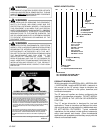
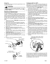
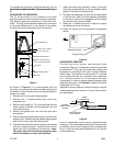
To complete the conversion, slide the evaporator coil into
the chassis and attach the three (3) access panels.
(Figure
7).
CONVERSION TO HORIZONTAL
The “B” series product is not suitable for horizontal
application and must not be used for this type of installation.
The following describes converting to “Horizontal Left-
Hand”. The only field modification required for conversion
to “Horizontal Right-Hand” is the removal of the plastic
knockouts in the horizontal panel drain connections.
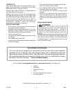
TOP OF WRAPPER
INSULATION JACKET
ZEE COIL SUPPORT
WRAPPER STIFFENER
DRAIN PAN INSULATION
DPI KIT (HATCHED AREA)
NEOPRENE GASKET
MOTOR
BLOWER
Figure 7
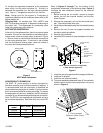
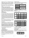
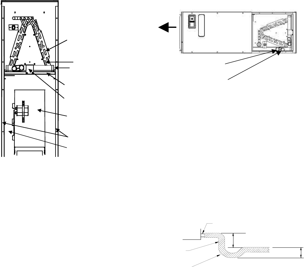
As shown in Figure 8, it is recommended that the
conversion to horizontal be performed before placing the
air handler in its final location and in an area that allows for
access to all sides.
1. Remove the (3) air handler access panels.
2. Remove the “J” shaped bracket that retains the
evaporator coil.
3. Remove the flowrater (or TXV) from the lower left side
access panel and slide out the evaporator coil and
horizontal drain pan.
4. Remove the gasket from the horizontal pan drain
connections.
5. Remove the oval shaped plastic plug from the left side
access panel. Remove the oval shaped rubber gasket
seal from the lower right side access panel.
6. The drain connections for the horizontal pan are sealed
with a thin coating of plastic. Carefully knock out this
plastic seal with a screwdriver and hammer. Note:
The upper drain will become the secondary drain
which is mandatory in many municipalities .
7. Install the plastic plug removed in step 5 to the right
side lower access panel and the oval shaped rubber
gasket to the lower left access panel.
8. Reinstall the evaporator coil with the horizontal panel
on the left side. Note: Push the assembly completely
to the rear to ensure the engagement of the upflow
pan with the rear channel bracket.
9. Install the “J” bracket (removed in step 2) to support
the upflow pan to the tie channel.
10. Attach all panels and the refrigerant management
device.
Secondary Drain
Primary Drain
Figure 8
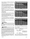
CONDENSATE REMOVAL
The drain pan has a primary and secondary drain
connection (Figure 8). Condensate removal is performed
by attaching a ¾” PVC pipe to the evaporator coil pan and
terminated in accordance with local or state Plumbing/
HVAC codes. The installation must include a “P” style trap
that is located as close as is practical to the evaporator
coil. Exercise caution not to over-tighten the drain
connection(s) in order to prevent possible damage to the
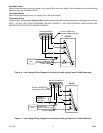
evaporator drain pan. See Figure 9 for details of a typical
condensate line “P” trap.
Installations that are above a finished ceiling may require
a field supplied auxiliary drain pan. Consult local codes on
this requirement.
DRAIN
CONNECTION
2" MINIMUM
3" MINIMUM
POSITIVE LIQUID
SEAL (REQ'D)
UNIT
FLEXIBLE
TUBING (HOSE
OR PIPE)
Figure 9
Use of a condensate removal pump is permitted when
necessary. This condensate pump should have provisions
for shutting off the control voltage should a blocked drain
occur. A trap must be installed between the unit and the
condensate pump.