


7
IO-230F 08/04
Piping Size
For the correct tubing size, follow the specification for the
condenser/heat pump.
WARNING
THIS COIL IS SHIPPED UNDER PRESSURE. FOLLOW
THESE INSTRUCTIONS TO PREVENT INJURY (SEE
FIGURES 1 AND 2).
Evaporator Coil Metering Devices
Flowrater Models (ARUF and ARPF)
For most installations no change to the flowrater orifice is
required. In mix-matched applications (condenser/heat
pump is a different tonnage than the air handler), a different
flowrater orifice may be required. See the Goodman piston
kit chart PKC-00 or latest revision. Consult your local
distributor for the details regarding mix-matched orifice
sizing.
1. Loosen the 13/16 nut 1 TURN ONLY. No pressure loss
indicates possible leak.
2. Remove the nut and discard the black or brass cap.
3. Remove the check piston to verify it is correct. See
piston kit chart in instructions.
4. Use a tube cutter to remove the spin closure on the
suction line.
5. Remove the tailpiece clamped to the exterior.
6. Slide the 13/16 nut into position. Braze tailpiece to
the liquid tube.
7. Insert the suction line into the connection, slide the
insulation and the rubber grommet at least 18" away
from the braze joint.
8. AFTER THE TAILPIECE HAS COOLED, position the
white Teflon seal and hand tighten the nut.
9. Torque the 13/16 nut to 20-30 ft-lbs. [2.77-4.15 meter
kg].
10. Replace suction line grommet and insulation.
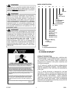
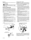
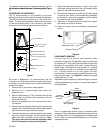
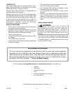
TAILPIECE
13/16" NUT
PLASTIC or BRASS CAP
WHITE
TEFLON SEAL
PISTON
APPLY FLOWRATER
GASKET FOR AIR
TIGHT APPLICATION
Figure 1
RUBBER
GROMMET
SUCTION LINE
WITH SPIN CLOSURE
Figure 2
TXV Models (ARPT and AEPT)
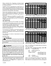
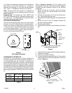
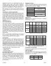
IMPORTANT NOTE: In order to prevent damage to the
sensing bulb, it is not permanently installed in the factory.
This bulb is to be removed prior to brazing. Place in proper
location after braze joint has cooled (Figure 3).
1. Loosen the 13/16 nut 1 TURN ONLY. No pressure
loss indicates possible leak.
2. Remove the nut and discard the black or brass cap.
3. Remove large front panel and remove sensing bulb
from suction manifold. TO PREVENT DAMAGE TO
SENSING BULB, ENSURE BULB IS NOT NEAR
FLAME OR IN CONTACT WITH SUCTION LINE OR
MANIFOLD DURING BRAZING.
4. Use a tube cutter to remove the spin closure on the
suction line.
5. Remove the tailpiece clamped to the exterior.
6. Slide the 13/16 nut into position (Figure 1). Braze
tailpiece to liquid tube.
7. Insert the suction line into the connection, slide the
insulation and the rubber grommet at least 18" away
from the braze joint.
8. AFTER THE TAILPIECE HAS COOLED, position the
white Teflon seal and hand tighten the nut.
9. Torque the 13/16 nut to 20-30 ft-lbs. [2.77-4.15 meter
kg].
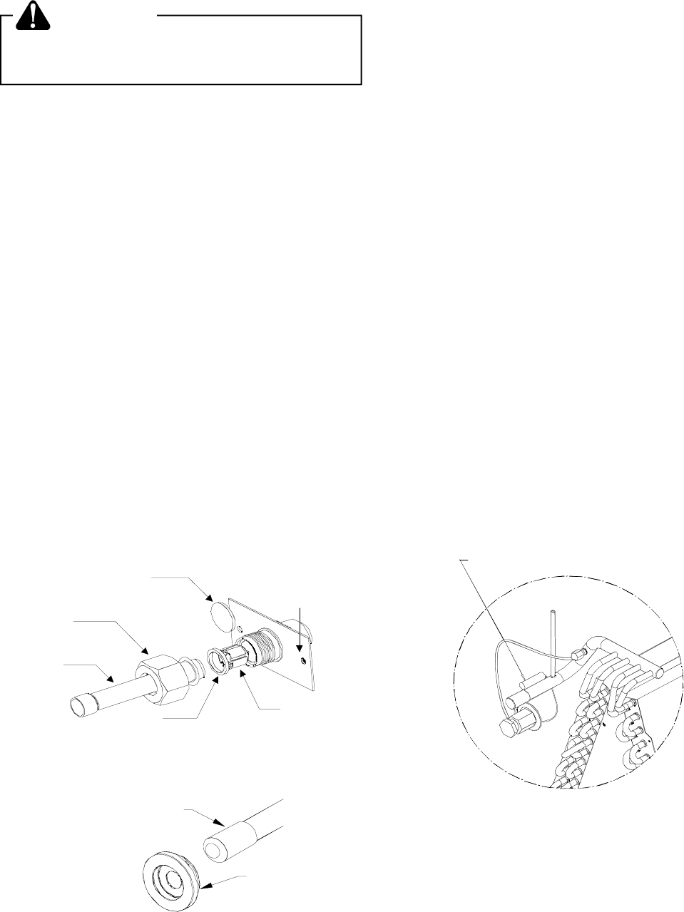
10. Replace sensing bulb to horizontal portion of suction
line (Figure 3) just inside cabinet. Place bulb parallel
with suction line in the 10 o’clock position. If 10 o’clock
position is inaccessible, place in the 2 o’clock position.
Secure bulb to line with strapping provided in literature
envelope. Insulate sensing bulb to line with self-
adhesive insulation provided in envelope.
11. Replace access panel, suction line grommet, and
insulation.
REATTACH BULB HERE USING
STRAPPING AND INSULATION
PROVIDED
Figure 3
For the majority of installations, no adjustment to the TXV
setting is required. However, if the measured superheat is
less than 8° or greater than 20°, an adjustment is required.
The adjustment stem is at the base of the valve (opposite
the diaphragm) under the flare nut.