


5
IO-230F 08/04
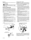
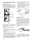
maximum heat and allow the system to reach steady state
conditions. Insert two thermometers, one in the return air
and one in the supply air. The temperature rise is the supply
air temperature minus the room air temperature.
Use HKR specification sheets to determine the HKR
available for a given air handler.
HKR INSTALLATION
Follow instructions listed in Installation and Operating
Instructions shipped with the heat kit.
LOCATION
WARNING
THIS AIR HANDLER IS DESIGNED FOR INDOOR
INSTALLATION ONLY. DO NOT INSTALL OUTDOORS.
When installing this air handler consideration to minimize
the length of refrigerant tubing is to be given. Do not install
the air handler in a location either above or below the
condenser that violates the instructions provided with the
condenser. The clearance from a combustible surface to
the unit is 0". However, service clearance is to take
precedence. Allow a minimum of 24" in front of the unit for
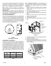
service clearance. When installing in an area directly over
a finished ceiling (such as an attic), an emergency drain
pan is required directly under the unit. See local and state
codes for additional requirements. When installing this unit
in an area that may become wet, elevate the unit with a
sturdy, non-porous material. In installations that may lead
to physical damage (i.e. a garage) it is advised to install a
protective barrier to prevent such damage.
DUCTWORK
This air handler is designed for a complete supply and
return ductwork system.
CAUTION
DO NOT OPERATE THIS PRODUCT WITHOUT ALL
DUCTWORK ATTACHED.
To ensure correct system performance, the ductwork is to
be sized to accommodate 375-425 CFM per ton of cooling
with the static pressure not to exceed .5" WC. Inadequate
ductwork that restricts airflow can result in improper
performance and compressor or heater failure. Ductwork
is to be constructed in a manner that limits restrictions and
maintains suitable air velocity. Ductwork is to be sealed to
the unit in a manner that will prevent leakage.
Return Ductwork. DO NOT TERMINATE THE RETURN
DUCTWORK IN AN AREA THAT CAN INTRODUCE
TOXIC, OR OBJECTIONABLE FUMES/ODORS INTO
THE DUCTWORK. The return ductwork is to be introduced
into the air handler bottom (upflow configuration).
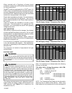
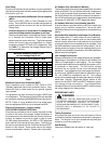
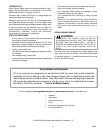
Return Air Filters. Each installation must include a return
air filter. This filtering may be performed at the air handler
or externally such as a return air filter grille. Air handlers
mounted in the downflow orientation, including “B” series,
require external filtering. A washable filter is available as
an accessory. To ensure optimum performance frequent
filter cleaning is advised. Refer to
Table 5 for the appropriate
filter.
ARUFor
ARPT
model
ARPF
model
AEPT
model
Filter
Number
Qty
Required
018-032 024, 036 n/a FIL 18-32 1
036-042 n/a 30 FIL 36-42 1
048-061
048, 060
036, 060
FIL 48-61
1
Table 5
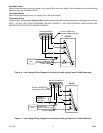
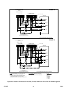
ELECTRICAL SUPPLY WIRE AND MOP
WARNING
TO AVOID THE RISK OF FIRE OR EQUIPMENT DAMAGE,
USE ONLY COPPER CONDUCTORS. BEFORE
SERVICING OR INSTALLING THIS EQUIPMENT, THE
ELECTRICAL POWER TO THIS UNIT MUST BE IN THE
“OFF” POSITION AND ALL POWER SUPPLIES
DISCONNECTED.
CAUTION
MORE THAN ONE DISCONNECT MAY EXIST. FAILURE
TO OBSERVE THIS WARNING MAY RESULT IN AN
ELECTRICAL SHOCK THAT CAN CAUSE PERSONAL
INJURY OR DEATH.
WARNING
THE UNIT MUST HAVE AN UNINTERRUPTED,
UNBROKEN ELECTRICAL GROUND TO MINIMIZE THE
POSSIBILITY OF PERSONAL INJURY IF AN ELECTRICAL
FAULT SHOULD OCCUR. THE ELECTRICAL GROUND
CIRCUIT MAY CONSIST OF AN APPROPRIATELY SIZED
ELECTRICAL WIRE CONNECTING THE GROUND LUG
IN THE UNIT AND CONTROL BOX WIRE TO THE
BUILDING’S ELECTRICAL SERVICE PANEL. OTHER
METHODS OF GROUNDING ARE PERMITTED IF
PERFORMED IN ACCORDANCE WITH THE “NATIONAL
ELECTRIC CODE” (NEC)/”AMERICAN NATIONAL
STANDARDS INSTITUTE” (ANSI)/”NATIONAL FIRE
PROTECTION ASSOCIATION” (NFPA) 70 AND LOCAL/
STATE CODES. IN CANADA, ELECTRICAL GROUNDING
IS TO BE IN ACCORDANCE WITH THE CANADIAN
ELECTRIC CODE CSA C22.1. FAILURE TO OBSERVE
THIS WARNING CAN RESULT IN ELECTRICAL SHOCK
THAT CAN CAUSE PERSONAL INJURY OR DEATH.
Inspection of the Building Electrical Service
This unit is designed for single-phase electrical supply. DO
NOT OPERATE ON A THREE-PHASE POWER SUPPLY.
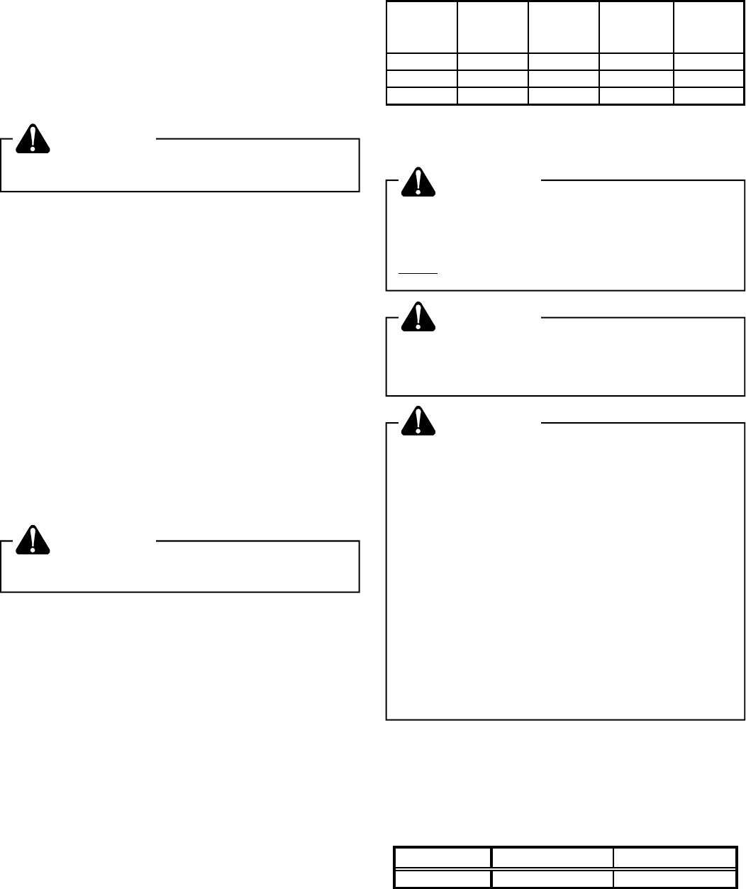
Measure the power supply to the unit. The supply voltage
must be in agreement with the unit nameplate power
requirements and within the range shown in Table 6.
Nominal Input Minimum Voltage Maximum Voltage
208/230 187 253
Table 6