


10
IO-230F 08/04
IMPORTANT NOTE: THE EVAPORATOR COIL IS
COATED WITH OILS THAT MAY DISSOLVE
STYROFOAM AND CERTAIN TYPES OF PLASTICS.
THEREFORE, A REMOVAL PUMP OR FLOAT SWITCH
MUST NOT CONTAIN ANY OF THESE MATERIALS.
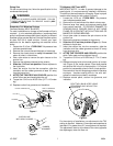
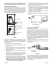
Tip: Priming the “P” trap may avoid improper draining at
the initial installation and at the beginning of the cooling
season.
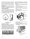
ACHIEVING 2% LOW LEAKAGE RATE
Ensure that the Neoprene gasket with PSA remains intact
on all surfaces that the access panels are secured to.
These surfaces are the entire length of the wrapper and
areas between the upper tie plate, upper and lower access
panels. Be sure that upper access panel breaker insert
gasket is intact and also flowrator gasket is installed on
the lower access panel. An additional drain hole cover is
required.
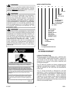
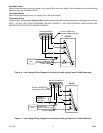
ARUF/ARPF MOTOR
Motor Speed Adjustment
The motors in all ARUF and ARPF motors are multi-speed
PSC motors. The color of the wire coming from the motor
to the “COM” terminal on the control board defines in which
speed the motor will operate. The black wire represents
high speed, the red wire represents low speed, and the
blue wire (select models only) represents medium speed.
To change speeds, remove the wire attached to the “COM”
terminal on the control board, and swap it with the wire (on
terminal “M1” or “M2”) with the color that will give the
desired speed.
NOTE: In some models, not all speed taps are allowable
for certain electric heat applications. Refer to air handler
Series and Ratings plate for minimum speed.
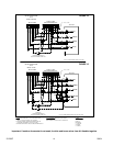
AEPT MOTOR
This section references the operation characteristics of
the AEPT model motor only. The ECM control board is
factory set with dipswitch #4 in the “ON” position and all
other dipswitches in the “OFF” position. For most
applications this setting is to be changed according
to the electric heat size and the outdoor unit selection.
The AEPT product uses a General Electric ECM
TM
motor.
This motor provides many features not available on the
traditional PSC motor. These features include:
• Improved Efficiency
• Constant CFM
• Soft Start and Stop
• Improved Humidity Control
Motor Speed Adjustment
Each ECM
TM
blower motor has been preprogrammed for
operation at 4 distinct airflow levels when operating in
Cooling, H.P. Heating, Backup Heating (Electric Heating),
and Backup + H.P. Heating. Each mode has 4 levels to
deliver different Air Flow CFM [L/s]. The adjustment is
performed by changing the dipswitch(s) either to an “OFF”
or “ON” position.
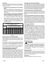
Dipswitch Functions
The AEPT air handler motor has an electronic control that
contains an eight (8) position dip switch. The function of
these dipswitches are shown in Table 9.
Dipswitch Number Function
1
2
3
N/A
4
Indoor Thermostat
5
6
7
8
Cooling & Heat Pump CFM
CFM Trim Adjust
Table 9
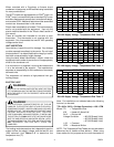
Electric Heat
CFM Delivery
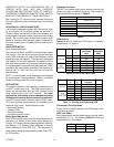
Tables 10 and 11 show the CFM output for dipswitch
combinations 1-2, and 5-6.
Switch Switch
1 2
OFF OFF 1100 1210
ON OFF 850 935
OFF ON
700 775
AEPT36
OFF OFF
2050 2150
and
ON OFF
1750 1835
AEPT60
OFF ON
1600 1680
ON ON
1200 1260
Model
TABLE 10 - ELECTRIC HEAT CFM
AEPT30
EMERGENCY
(ELECTRIC)
HEAT
HP
w/BACKUP
HEAT
Switch Switch
5 6
OFF OFF 2 ½ 1100
ON OFF 2 800
OFF ON
1 ½
600
AEPT36
OFF OFF
5 1800
and
ON OFF
4 1580
AEPT60 OFF ON
3 ½
1480
ON ON
3
1200
Table 11 - Cooling and Heat Pump CFM
Nominal Cooling
Tonnage
AEPT30
Model CFM
Thermostat “Fan Only Mode”
During “Fan Only Mode” operation, the CFM output is 30%
of the cooling setting.
CFM Trim Adjust
Minor adjustments can be made through the dip switch
combination of 7-8. The following Table 12 shows the
switch position for this feature.
CFM Switch 7 Switch 8
+10% ON OFF
-15% OFF ON
Table 12