


8
IO-230F 08/04
To increase the superheat (measured at the condenser
base valve), turn the stem clockwise (in). Similarly, to
decrease the superheat, turn the stem counterclockwise
(out). Use a ¼ “ refrigeration wrench for this function.
Note: Design point for the system is 10 degrees of
superheat (measured at the condenser base valve) at 95
degree outdoor air.
Charging Note: Air handlers with TXV’s (ARPT’s and
AEPT’s) should be charged to 15 degrees of subcooling at
the indoor inlet. This supercedes any subcooling value
listed with condensing unit’s literature.
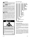
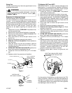
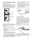
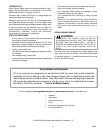
AEPT MOTOR ORIENTATION
If the unit is in the upflow position, there is no need to rotate
the motor. If the unit is in the downflow or horizontal position,
loosen motor mount and rotate motor as shown in Figure
4. Be sure motor is oriented with the female connections
on the casing pointing down. If the motor is not oriented
with the connections pointing down, water will collect in
the motor and cause premature failure.
FRONT VIEW
FOR OPTIONAL
SAFETY GND USE
MOUNTING BOLTS
SIDE VIEW
FEMALE CONNECTIONS
Figure 4
AEPT Motor Orientation
CONVERSION TO DOWNFLOW
The ARPF “B” series product is factory equipped for
downflow operation and no field conversion is required. It
is recommeneded that the conversion to downflow be
performed before placing the air handler in its final location
and in an area that allows for access to all sides. To prevent
the evaporator coil pan from “sweating” the DPI accessory
insulation kit is to be used when performing this conversion.
Note: The DPI kit is not supplied with this product and is to
be purchased separately. See Table 8 for the correct DPI
kit.
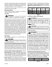
ARUFor ARPT
model
AEPT model Insulation Kit
018-032 n/a DPI18-30/20
036-042 30 DPI36-42/20
048-061
036, 060
DPI48-61/20
Table 8
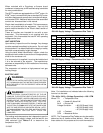
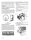
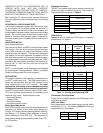
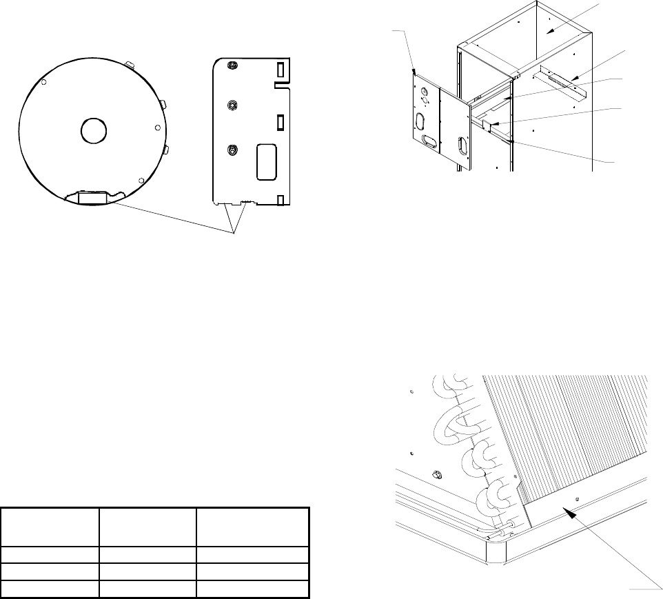
Refer to Figures 5 through 7 for the location of the
components referenced in the following steps. Figure 5
illustrates the new installation location for the removed
components.
1. Before inverting the air handler, remove all access
panels, the coil rear channel bracket, and the filter
close-off panel.
2. Remove the evaporator coil and the horizontal drain
pan. Discard horizontal drain pan.
3. Install the provided plastic plug into the vacated access
panel.
4. Remove the two (2) zee coil support brackets and
insulation retaining brackets.
5. Remove the tie bracket.
6. Install the DPI Insulation Kit onto the bottom of the drain
pan.
Return Air Side
of Unit
Rear
Channel
Bracket
Zee Coil
Support Bracket
Access
Panel
Coil Retaining
Bracket
NOTE: The filter provision is not applicable
in THIS downflow application.
Tie Bracket
Figure 5
7. Install the zee coil supports and the wrapper stiffeners.
8. Install the tie bracket.
9. Install the rear channel bracket.
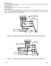
10. To prevent possible condensate “blow off” the insulation
retainers are to be laid into the evaporator coil pan as
shown in Figure 6.
3" Flat Insulation
Retainer (Both Sides)
Figure 6